
In this tutorial we cover the following topics
- Flyback diodes and voltage spike suppression with signal diodes
- Convert AC voltage into fixed DC voltage with signal (or power) diodes and Zener diodes
To have the current flowing through the conductor there must be a some kind of a force pushing the charges through the conductor. This force is named an electromotive force (EMF, denoted ${\mathcal {E}}$). The word force in this case is not used to mean mechanical force, measured in newtons, but a potential, or energy per unit of charge, measured in volts. A device that, by doing work on charge carries, maintaina a potential difference between its terminals, causing a current to flow in an electrical circuit or device, is called a source of electromotive force or simply electromotive force. EMFs convert other form of energy:
- battery - chemical energy,
- electric generator - mechanical energy,
- solar cell - electromagnetic radiation,
into electrical energy. The product of such a device is also known as EMF.
Electromotive force $\mathcal{E}$ of a source is defined as:
$$
\mathcal{E}=\frac{W}{q} = \frac {P}{I},
$$
where:
- $W$ – work,
- $q$ – flowing charge,
- $P$ – power dissipated in the circuit,
- $I$ – electric current.
The force on an electric charge depends on its location, speed, and direction; two vector fields are used to describe this force:
- The first is the electric field, which describes the force acting on a stationary charge and gives the component of the force that is independent of motion. An electric field is the physical field that surrounds electrically-charged particles and exerts force on all other charged particles in the field, either attracting or repelling them.
- The magnetic field, in contrast, describes the component of the force that is proportional to both the speed and direction of charged particles. Magnetic fields occur whenever charge is in motion. As more charge is put in more motion, the strength of a magnetic field increases.
Whenever current travels through a conductor, a magnetic field is generated. This was discovered in 1820 by Danish physicist Hans Christian Ørsted, when he noticed that the needle of a compass next to a wire carrying current turned so that the needle was perpendicular to the wire. He investigated and discovered the rules which govern the field around a straight current-carrying wire:
- The magnetic field lines encircle the current-carrying wire.
- The magnetic field lines lie in a plane perpendicular to the wire.
- If the direction of the current is reversed, the direction of the magnetic field reverses.
- The strength of the field is directly proportional to the magnitude of the current.
- The strength of the field at any point is inversely proportional to the distance of the point from the wire.
Although the contour of the magnetic field will vary depending on the shape of the conductor, if the conductor is a wire, the magnetic field always takes the form of concentric circles arranged at right angles to the wire. The magnetic field is strongest in the area closest to the wire, and its direction depends upon the direction of the current that produces the field.

|
On the image above, plus and minus signs indicate the poles of the battery (which is not shown) to which the wire is connected. Direction of current flow is indicated with an arrow (by convention, the current flow opposes the actual direction of the electrons flowing from minus to plus). The magnetic field lines generated around the wire due to the presence of the current are depicted in blue. The direction of the magnetic field around the wire is also indicated by the small arrows featured on the individual field lines. There is also a compass needle to clarify the direction of the field at any given point around the circumference of the wire.
There is a simple method of determining the direction of the magnetic field generated around a current-carrying wire commonly called the right hand rule. According to this rule, if the thumb of the right hand is pointed in the direction of the conventional current, the direction that the rest of the fingers need to curl in order to wrap around the wire is the direction of the magnetic field.
According to Ørsted observations, to generate a magnetic field we make a current flow through a wire, for example by connecting it to a battery. As we increase the current (amount of charge in motion) the field increases proportionally. As we move further away from the wire, the field we see drops off proportionally with the distance. Formaly this is described by Ampere's law which for long (circular) wire carrying current $I$ defines the magnetic field at a distance $r$ as:
$$
B = \frac{\mu_{0}I}{2\pi r}
$$
where $\mu_{0}$ is a constant known as the permeability of free space, $\mu_{0}=4\pi ⋅10^{−7} T \cdot m / A$.
An inductor, very often called a coil because of its shape, is a passive two-terminal electrical component that stores energy in a magnetic field when electric current flows through it.
Every inductor is characterized by its inductance (the ability to store energy in the magnetic field that is created by the flow of electrical current) denoted as $L$, which is the ratio of the voltage $v$ to the rate of change of current (EQ1):
$$
v(t) = L \frac{\textrm{d}i}{\textrm{d}t}
$$
As you know from previous subsection, a current $i$ flowing through a conductor generates a magnetic field around the conductor, which is described by Ampere's circuital law. If the current varies, the magnetic flux $\Phi$ through the circuit changes. By Faraday's law of induction, any change in flux through a circuit induces an electromotive force (EMF) or voltage v in the circuit, proportional to the rate of change of flux:
$$
v = \mathcal{E} = - \frac{\textrm{d}\Phi}{\textrm{d}t} = -L \frac{\textrm{d}i}{\textrm{d}t}
$$
The negative sign in the equation indicates that the induced voltage is in a direction which opposes the change in current that created it; this is called Lenz's law. The potential is therefore called a back EMF. If the current is increasing, the voltage is positive at the end of the conductor through which the current enters and negative at the end through which it leaves, tending to reduce the current. If the current is decreasing, the voltage is positive at the end through which the current leaves the conductor, tending to maintain the current. As a result, inductors oppose any changes in current through them.
Lenz’s law is a manifestation of the conservation of energy. The induced emf produces a current that opposes the change in flux, because a change in flux means a change in energy. Energy can enter or leave, but not instantaneously. Lenz’s law is a consequence. As the change begins, the law says induction opposes and, thus, slows the change. In fact, if the induced emf were in the same direction as the change in flux, there would be a positive feedback that would give us free energy from no apparent source—conservation of energy would be violated.
The term inductance was coined by Oliver Heaviside in 1886. It is customary to use the symbol $L$ for inductance, in honour of the physicist Heinrich Lenz. In the SI system, the unit of inductance is the henry (H), which is the amount of inductance that causes a voltage of one volt, when the current is changing at a rate of one ampere per second. It is named for Joseph Henry, who discovered inductance independently of Faraday. Inductors have values that typically range from 1 µH (10−6 H) to 20 H. Typically inductor consists of a wire wound into a coil or helix. A coiled wire has a higher inductance than a straight wire of the same length, because the magnetic field lines pass through the circuit multiple times, it has multiple flux linkages. The inductance is proportional to the square of the number of turns in the coil, assuming full flux linkage. Many inductors have a magnetic core made of iron or ferrite inside the coil, which serves to increase the magnetic field and thus the inductance. The magnetic field of the coil magnetizes the material of the core, aligning its magnetic domains, and the magnetic field of the core adds to that of the coil, increasing the flux through the coil. This is called a ferromagnetic core inductor. A magnetic core can increase the inductance of a coil by thousands of times.Along with capacitors and resistors, inductors are one of the three passive linear circuit elements that make up electronic circuits.
Some of the commonly known devices with inductors (also known as inductive loads) are motors, solenoid, electromagnetic relay, transformer etc. It's worth to note that even a small piece of wire or a trace on PCB can be considered as an inductor (or an inductive element) as it has inductance.
Types of Induction
There are two types of induction: self induction and mutual induction.
- When time varying current flows in a circuit the time varying flux is produced and this varying flux will link with that circuit itself and as a result there will be EMF induced in the circuit itself. This is a self induction.
- Mutual induction is when a change in current in one circuit causes a change in voltage across a second circuit as a result of a magnetic field that links both circuits. This effect is used in transformers.
- The increase in current causes a back EMF (voltage) across the inductor due to Faraday's law of induction which opposes the change in current.
- Since the voltage across the inductor is limited to the battery's voltage, the rate of increase of the current is limited to an initial value of (see above EQ1):
$$
\frac{\textrm{d}i}{\textrm{d}t}=\frac{v}{L}
$$ - The current through the inductor increases slowly as energy from the battery is stored in the inductor's magnetic field.
- Transformer.
- Graetz bridge $G$ made with four $D_{1}$ to $D_{4} rectifying diodes 1N4004$.
- The smoothing capacitor $1000\mu F$.
- Zener diode: 1N4733A with $P_{Z}=1.3W$ and $V_{Z}=5.1V.$
- The resisitor $R_{S}=51\Omega$ limit the current flow through the diode with $P_{max}=0.25W$.
- The load resisitor $R_{L}=1k\Omega$.
- Resistor $R_{S}$ become hot. It is not as hot as previously for $R_{S}=50\Omega$, we can say that it is stable hot, but anyway noticeably hot. Even with $R_{S}=1k\Omega$ resulting with $13.4mA$ current $R_{S}$ become hot as it is hot for $R_{S}=820\Omega$.
- Zener diode should keep voltage constant but when AC voltage is off, DC voltage is decreasing and along with it $V_{LED}$ is decreasing -- other words, despite the fact that decreasing $V_{S}$ voltage is (for a few seconds) grater than $V_{Z}$, $V_{LED}$ is also decreasing instead stays on the same $V_{Z}$ level as long as $V_{S} > V_{Z}$. And this happen regardless of the capacitance of the capacitors used (even if $4 \times 1000\mu$ are used).
- $V_{S}$ voltage is grater than $V_{Z}$ and
- current flowing through it is greater then minimum $I_{Z(min)}$ (typically 5-10mA).
- How to select $R_{S}$ so it wouldn't be hot?
- What should be changed to have (for a few seconds) stable $V_{Z}$ voltage when AC voltage is off.
PHASE 1
The following circuit shows a simple inductor connected to a a constant voltage source (a battery). The resistor represents a small internal resistance of the inductor's wire windings. There is also a switch.

|
When the switch is closed, the voltage from the battery is applied to the inductor, causing current from the battery's positive terminal to flow down to the negative terminal through the inductor and resistor. When the current starts to flow, the inductor builds up magnetic field and gets fully energized, i.e. the inductor inhibits the flow of current in the circuit while it building up energy. This process is in accordance with information provided in previous subsections:
PHASE 2
When the switch is opened, the current drops rapidly. As per Lenz’s law, the collapsing magnetic field induces a current in the circuit but in opposite direction. The inductor resists the drop in current by developing a very large induced voltage of polarity in the opposite direction of the battery. As a result, a negative potential is created on the inductor where there was once a positive potential due to forward flow of current. This is commonly known as Back EMF or Counter EMF or Flyback Voltage.

|
Now, due to the Flyback voltage, the inductor essentially becomes a power source with a significantly greater potential the actual power supply itself. For a 12V DC Power supply, the Flyback voltage spike can be few hundreds of volts. The high voltage spike is determined by the following equation (again see EQ1):
$$
v = L \frac{\textrm{d}i}{\textrm{d}t},
$$
where:
- $v$ is the voltage across the inductor,
- $L$ is the inductance,
- $\frac{\textrm{d}i}{\textrm{d}t}$ is the rate of change of current.
This means that the faster the current through the inductor is changed, the higher the voltage spike.
This voltage pulse, which can be much larger than the battery voltage, appears across the switch contacts. It causes electrons to jump the air gap between the contacts, causing a momentary electric arc to develop across the contacts as the switch is opened. The arc continues until the energy stored in the inductor's magnetic field is dissipated as heat in the arc. The arc can damage the switch contacts, causing pitting and burning, eventually destroying them. If a transistor is used to switch the current, for example in switching power supplies, the high reverse voltage can destroy the transistor.
PHASE 3
To prevent the inductive voltage pulse on turnoff, a diode is connected across the inductor as shown below

|
This diode is known as Flyback Diode or a Freewheeling Diode. The basic idea behind the use of a flyback diode is to provide an alternative path for the inductor for its current to flow. The diode doesn't conduct current while the switch is closed because it is reverse-biased by the battery voltage, so it doesn't interfere with normal operation of the circuit. However, when the switch is opened, the induced voltage across the inductor of opposite polarity forward biases the diode, and it conducts current, limiting the voltage across the inductor and thus preventing the arc from forming at the switch. The inductor and diode momentarily form a loop or circuit powered by the stored energy in the inductor. This circuit supplies a current path to the inductor to replace the current from the battery, so the inductor current does not drop abruptly, and it does not develop a high voltage. The voltage across the inductor is limited to the forward voltage of the diode, around 0.7 - 1.5V. This "freewheeling" or "flyback" current through the diode and inductor decreases slowly to zero as the magnetic energy in the inductor is dissipated as heat in the series resistance of the windings.
First indispensable component is the transformer. With this passive electrical device a harmful voltage from wall socket (230V) can be reduced to safe value.
|
|
In this type of rectifier four individual rectifying (signal, power) diodes are used connected in a closed loop "bridge" configuration to produce the desired output.

|
Four diodes labelled $D_{1}$ to $D_{4}$ are arranged in "series pairs" with only two diodes conducting current during each half cycle. This diode bridge circuit was invented by Polish electrotechnician Karol Pollak and patented in December 1895 in Great Britain and in January 1896 in Germany. In 1897, the German physicist Leo Graetz independently invented and published a similar circuit. Today the circuit is still referred to as a Graetz circuit or Graetz bridge.
During the positive half cycle of the supply, diodes $D_{2}$ and $D_{4}$ conduct in series while diodes $D_{1}$ and $D_{3}$ are reverse biased and the current flows through the load as shown below.

|
During the negative half cycle of the supply, diodes $D_{1}$ and $D_{3}$ conduct in series while diodes $D_{2}$ and $D_{4}$ are now reverse biased. The current flowing through the load in the same direction as before.

|
In consequence the current flowing through the load is unidirectional, so the voltage developed across the load is also unidirectional and the average DC voltage across the load is 0.637 of the peak voltage ($0.637V_{max}$, assuming no losses) or 0.9 of the effective voltage ($0.9V_{RMS}$, see RMS Voltage Tutorial for RMS explanation).
Because during each half cycle the current flows through two diodes instead of just one so the amplitude of the output voltage is two voltage drops ( $2 \cdot 0.7 = 1.4V$ ) less than the input $V_{max}$ amplitude. The ripple frequency is now twice the supply frequency (e.g. 100Hz for a 50Hz supply).
In our case we use four 1N4004 rectifier diodes to get full wave bridge rectifier.

|
| 1N4004 rectifier diode |
Although we can use four individual power diodes to make a full wave bridge rectifier, pre-made bridge rectifier components are available "off-the-shelf" in a range of different voltage and current sizes that can be used directly into a circuit.

|

|

|

|
| 1: KBU10M, 10A/1000V. 2 and 3: KBPC110, 3A/1000V. 4: 2W10, 2A/1000V. | |||
The resulting voltage produced by bridge rectifier implemented as it is showned on the image bellow

|
| Basic bridge circuit |
is not realy constant -- it forms a wave. To convert the full-wave rippled output of the rectifier into a more smooth DC output voltage a capacitor can be added. In our case, with 1000uF capacitor and 1kO load, the following results were obtained

|
| Basic bridge circuit with capacitor |
| AC with no load ($V_{1}$) | 14V |
| AC with load ($V_{1}$) | 14V |
| DC with no load ($V_{2}$) (image Basic bridge circuit) |
12.1V |
| DC with load ($V_{2}$) (image Basic bridge circuit) |
11.34V |
| DC with capacitor and no load ($V_{2}$) (image Basic bridge circuit with capacitor) |
18.75V |
| DC with capacitor and load ($V_{2}$) (image Basic bridge circuit with capacitor) |
17.1V |
The main drawback of the solution we have so far is a lack of stable voltage output. This could be achieved with a voltage regulator which main function is to provide a constant output voltage to a load connected in parallel with it in spite of the ripples in the supply voltage or variations in the load current. On of the simplest solution use a Zener diode which will continue to regulate its voltage until the diodes holding current falls below the minimum $I_{Z(min)}$ value in the reverse breakdown region (typically 5-10mA).
The Zener diode behaves just like a normal general-purpose diode consisting of a silicon PN junction and when biased in the forward direction, that is Anode positive with respect to its Cathode, it behaves just like a normal signal diode passing the rated current.

|
| 1N4733A Zener diode |
However, unlike a conventional diode that blocks any flow of current through itself when reverse biased, that is the Cathode becomes more positive than the Anode, as soon as the reverse voltage reaches a pre-determined value $V_{Z}$, the zener diode begins to conduct in the reverse direction if only current is greater than $I_{Z(min)}$. That is why a zener diode is always operated in its reverse biased condition. As such a simple voltage regulator circuit can be designed using a zener diode to maintain a constant DC output voltage across the load in spite of variations in the input voltage or changes in the load current.
The zener voltage regulator circuit consists of a current limiting resistor $R_{S}$ connected in series with the input voltage $V_{S}$ with the zener diode connected in parallel with the load $R_{L}$ in this reverse biased condition. Because the load is connected in parallel with the zener diode, so the voltage across $R_{L}$ is always the same as the zener voltage $V_{Z}$ ($V_{R}$ = $V_{Z}$). Other words, the stabilised output voltage is always selected to be the same as the breakdown voltage $V_{Z}$ of the diode. The supply voltage $V_{S}$ must be greater than $V_{Z}$.

|
| Basic Zener diode circuit |
Resistor $R_{S}$ is connected in series with the zener diode to limit the current flow through the diode. By passing a small current through the diode from a voltage source, the zener diode will conduct sufficient current to maintain a voltage drop of $V_{out}$. With no load connected to the circuit, the load current will be zero, and all the circuit current passes through the Zener diode which in turn dissipates its maximum power. Also a small value of the series resistor $R_{S}$ will result in a greater diode current when the load resistance $R_{L}$ is connected and large as this will increase the power dissipation requirement of the diode so care must be taken when selecting the appropriate value of series resistance so that the zener’s maximum power rating is not exceeded under this no-load or high-impedance condition.
There is a minimum zener current $I_{Z(min)}$ for which the stabilisation of the voltage is effective and the zener current must stay above this value operating under load within its breakdown region at all times. The upper limit of current is of course dependant upon the power rating of the device.
Let's do some calculations to make real working circuit.
W will use 1N4733A Zener diode with the 1.3W maximum power rating $P_{Z}$ with the Zener voltage $V_{Z}$ ranges from 4.845V to 5.355V with typical value 5.1V. With this parameters the maximum current flowing through the Zener diode can be calculated as follow
$$
I_{max} = \frac{Watts}{Voltage} = \frac{1.3}{5} = 0.26A = 260mA
$$
Having the maximum current flowing through the Zener diode we can calculate minimum value of resistor $R_{S}$
$$
R_{S} = \frac{V_{S}-V_{Z}}{I_{Z}} = \frac{18V-5V}{260mA} = \frac{13V}{0.26A} = 50 \Omega
$$
For tests we will use one $51 \Omega$$ resistor (green-brown-black) with the 0.25W maximum power rating. Applying all the components
to the above circuit we got a working circut. Unfortunately when turn on, within just a second, a smell can be detected and resistor $R_{S}$ became VERY HOT.
Something has gone wrong. Simple calculatons explains what. Power rating for $R_{S}$ in this configuration can be calculated as follow
$$
P_{R_{S}} = I_{R_{S}} \cdot V_{R_{S}} = 0.26A \cdot 13V = 3.38W
$$
3.38W is much greater value than $P_{max}$ for $R_{S}$ which is 0.25W. So either resistor with higher power rating or resistor with higher resistance should be choosen. Considering second option, we calculate
$$
I_{R_{S}} = \frac{P_{R_{S}}}{V_{R_{S}}} = \frac{0.25W}{13V} = 0.019A = 19mA
$$
Now we know that if voltage is 13V and current 19mA than power raiting should reach $P_{max}=0.25W$ for resistor $R_{S}$. The resistance for $R_{S}$ in that case is equal to
$$
R_{S} = \frac{V_{S}-V_{Z}}{I_{R_{S}}} = \frac{13V}{0.019A} = 684.2\Omega
$$
To have some safety margin we choose $R_{S}=820\Omega$ (gray-red-violet) and in that case
$$
I_{R_{S}} = \frac{V_{S}-V_{Z}}{R_{S}} = \frac{13V}{820\Omega} = 0,0158A = 15.8mA
$$
Before we check if the way we think expressed in a previous section is correct, let's make a target circuit, that is a AC to DC fixed voltage convert with diodes and LED load as it is showned below

|
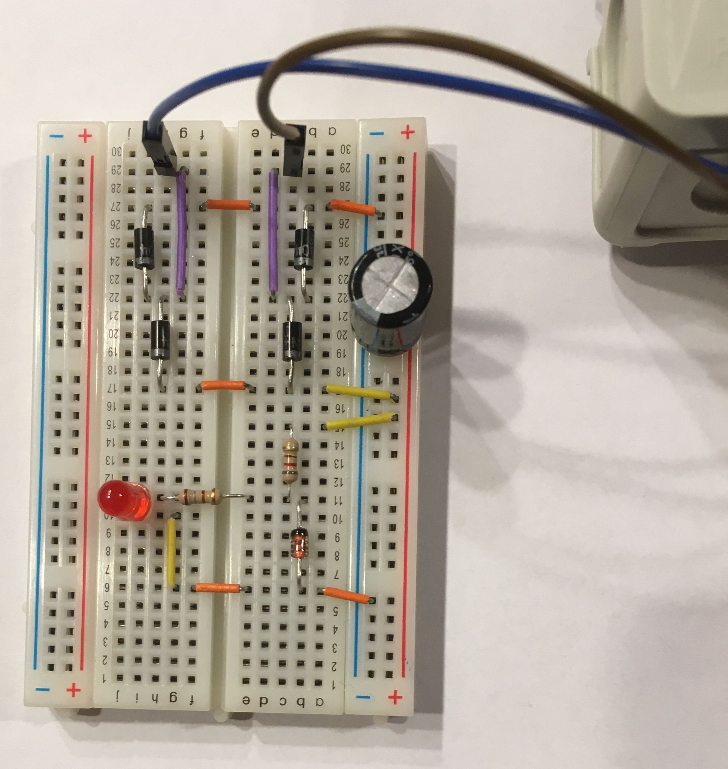
|
| Left: Scheme of AC to DC fixed voltage convert with diodes and LED load. Right: Close to real view of a schema from left image | |
Resistor $R_{LED}$ may be calculated as follow
$$
R_{LED} = \frac{V_{Z}-V_{LED}}{I_{LED}} = \frac{5V-2.5V}{0.015} = 166,6\Omega
$$
We took $R_{LED} = 180 \Omega$ (brown-gray-brown). To verify all our previous calculations a voltmeter and ammeter (from Ampere Meter) can be attached as it is showned below

|
In this configuration measured values were as follow
| $V_{1} = V_{S} = 17.27V$ |
| $A_{1} = A_{R_{S}} = 0.0157A = 15.7mA$ |
| $A_{2} = I_{D_{Z}} = 0.8mA$ |
| $V_{2} = V_{LED} = 4.77V$ |
| $A_{3} = I_{LED} = 0.148A = 14.8mA$ |
When turn on, everything seems to be working correctly but
Problem number 2 could be explained in the following way. Zener diode keeps voltage stable on (more or less) $V_{Z}$ level as long as
The second condition is not fulfilled in our case.
The questions are
One of the possible solution is reducing LED ($A_{3} = I_{LED}$) current. The following configurations were tested
| $R_{LED}$ [$\Omega$] | $A_{3} = I_{LED}$ [mA] | $A_{2} = I_{D_{Z}}$ [mA] | Comment |
| 270 red-violet-brown |
10.9 | 4.58 | Voltage $V_{2} = = V_{LED}$ drops rapidly when AC is off even when $4 \times 1000 \mu F$ capacitors are used |
| 300 orange-black-brown |
10.1 | 5.35 | |
| 330 orange-orange-brown |
9.38 | 6.1 | |
| 360 orange-blue-brown |
8.58 | 6.9 | |
| 430 yellow-orange-brown |
7.38 | 7.95 | Voltage $V_{2} = V_{LED} > 4.9V$ for 3 seconds when $4 \times 1000 \mu F$ capacitors are used. Voltage $V_{2} = V_{LED} > 4.9V$ for 1.5 seconds when $2 \times 1000 \mu F$ capacitors are used. |