
Last update: 2023-10-24
In this tutorial you will learn what a pull resistors is and why you need them when you use buttons.
Table of contents:
Take the Arduino board and make the following test
- Select one of digital pin, say pin number 2, and call it
PIN_IN. - Read periodically it's state and if is
HIGHturn on Arduino's built in LED and turn off if isLOW. - Reset or turn off and turn on Arduino and again observe LED state.
- What can you say about LED?
Below tere is a code you can use to make this test.
|
1 2 3 4 5 6 7 8 9 10 11 12 13 14 15 16 17 |
#define PIN_IN 2 // Digital pin 13 has a build-in LED attached to it #define PIN_LED 13 int ledState = 0; void setup() { // put your setup code here, to run once: pinMode(PIN_IN, INPUT); // Set the digital pin PIN_IN as input pinMode(PIN_LED, OUTPUT); // Set the digital pin PIN_LED as output } void loop() { // put your main code here, to run repeatedly: ledState = digitalRead(PIN_IN); // Read from the input pin PIN_IN digitalWrite(PIN_LED, ledState); // Set the LED to the input's state } |
Read an appropriate documentation if you don't know how function you used are working
What can you say about LED behaviour? Is it predictible and stady? Souldn't be. Our LED shoul be sometimes on but sometimes off. This means that sometimes you read
HIGH state but other time opposit, LOW, state. Sometimes high, sometimes low is like a wave: sometimes up, sometimes down so you say that state of the pin is floating.
Sometimes it could be difficult to observe this behaviour. You can try with another board or repeat test another time.
Another solution to observe this is to use two wires: one connected to our PIN_IN and second to 5V.

|
Next connect both wires - logical state on
PIN_IN should be HIGH and led turn on. Disconnect wires - logical state on PIN_IN should be LOW and led turn off.
In my case, whatever I do, led stays on.

|
| Initila state |

|
| Wires connected - led is on |

|
| Wires disconnected - led is still on |
There are no any premises so you could say which state,
HIGH or LOW, would be read on our pin PIN_IN. The input is "free" - that is, it doesn't have a solid connection to voltage or ground, and it will randomly return either HIGH or LOW. In this case situation is similar to the following piece of code
|
1 2 3 4 5 6 7 8 9 |
#include <stdio.h> int main(){ int input; printf("%d\n", input); return 0; } |
The input variable stays uninitialized so its value is random. Every time you run this program, results are different.
MacBook-Air-Piotr:tutorials_electronics_pull_resistors fulmanp$ gcc test_01.c

MacBook-Air-Piotr:tutorials_electronics_pull_resistors fulmanp$ ./a.out

97525814

MacBook-Air-Piotr:tutorials_electronics_pull_resistors fulmanp$ ./a.out

256753718

MacBook-Air-Piotr:tutorials_electronics_pull_resistors fulmanp$ ./a.out

211959862

MacBook-Air-Piotr:tutorials_electronics_pull_resistors fulmanp$ ./a.out

294740022

MacBook-Air-Piotr:tutorials_electronics_pull_resistors fulmanp$ ./a.out

224059446

MacBook-Air-Piotr:tutorials_electronics_pull_resistors fulmanp$
Sometimes, when you run it over and over again in short time interval results are the same but make a brake and run it after one hour or another day - results should be different.
Same with our digital pin - it stays uninitialized. The question is: How to initialize pins?
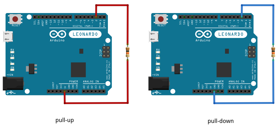
To prevent this unpredictible behaviour, a pull-up or pull-down resistor are used to ensure that the pin is in either a
HIGH or LOW state, while also using a low amount of current.
|
As you can see, our
PIN_IN is connected with either 5V to get always HIGH state or with GND to get always LOW state. To limit a current a 10kOhms resistor is used (limiting current to 0.5mA) but any value in range 4.7kOhms-15kOhms will do in this case. Keep in mind that the larger the resistance for the pull, the slower the pin is to respond to voltage changes.
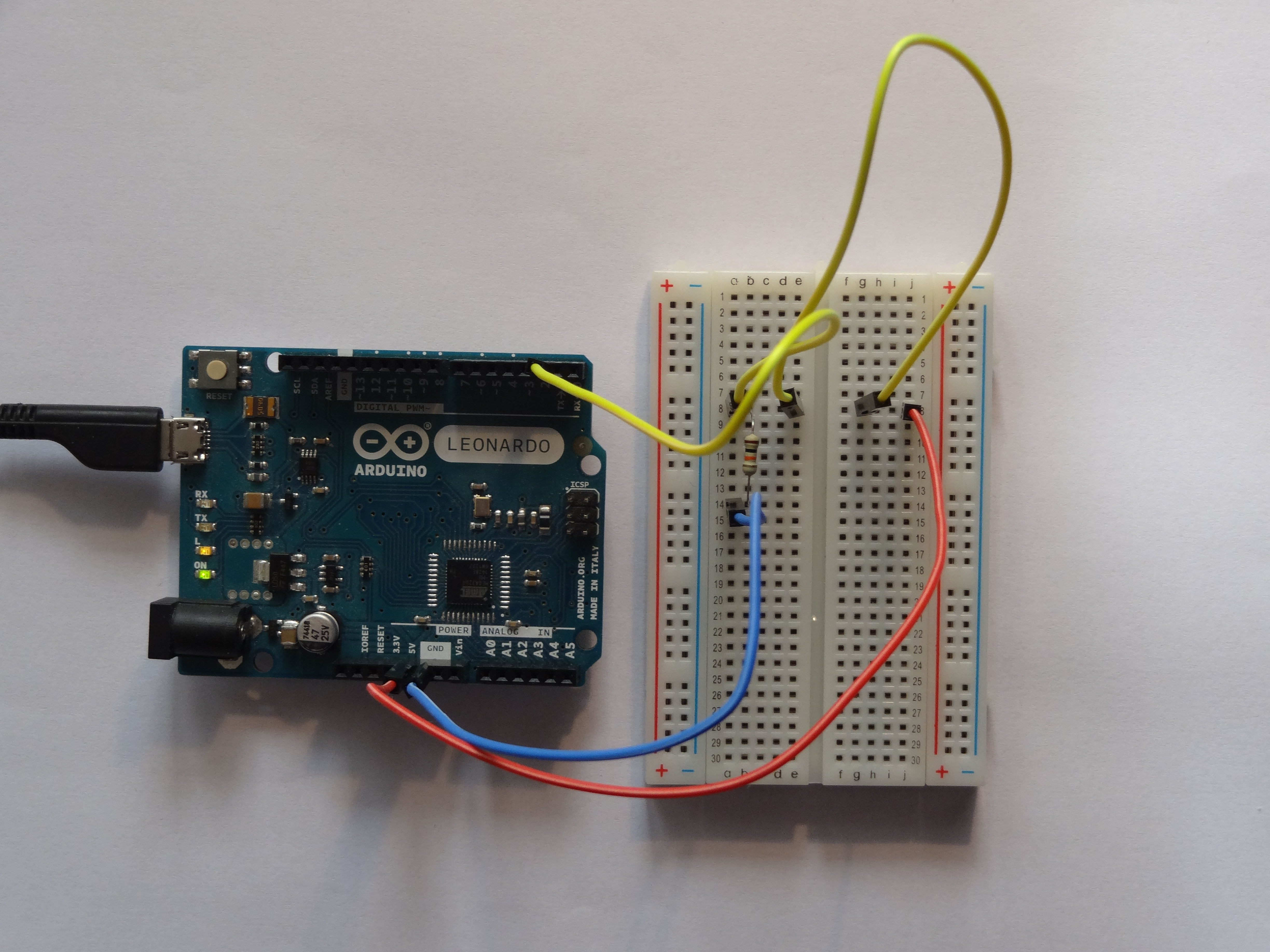
Let's try to fix our test case from Test 1 section.

|

|

|
Left image: pull-up active, led is on. Right image: PIN_IN is connected with GND and led is off. |
|

|
|
Left image: pull-down active, led is off. Right image: PIN_IN is connected with 5V and led is on. |
|
Of course you can replace bare wires with switches

|
Unfortunately switches becomes a source of a new problems.
Take a pull-down version from the previous section and write a program which changes counter value every time you press the button.
Below there is a code you can use to make this test.
|
1 2 3 4 5 6 7 8 9 10 11 12 13 14 15 16 17 |
#define PIN_IN 2 #define PIN_LED 13 int counter = 0; void setup() { pinMode(PIN_IN, INPUT); pinMode(PIN_LED, OUTPUT); Serial.begin(9600); } void loop() { if(digitalRead(PIN_IN) == HIGH){ counter ++; } Serial.println(counter); } |
The counter seems to behave unpredictably. Sometimes it is increased by 1, other times by much grater value like 10 or 15.
The problem is that
- what for us (humans) is immediate for microcontrollers takes ages;
- even such a simple "devices" like switch have its physical limits;
- voltage characteristic of switch is far from ideal model.
You believe that voltage characteristiv of switch looks like
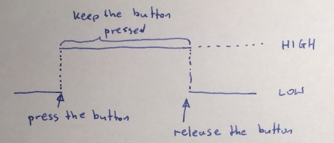
Unfortunately, because of physical limits and properties, real characteristic is like
Todo (id=no todo id): pull_resistors: use osciloscope to visualize this

Todo (id=no todo id): pull_resistors: improve images
So, when you press the button, there is a very short time interval (very short for us not for a microcontroller) when membrane of our switch oscillates (bounces) and thus you can observe a series of HIGH and LOW state. When our microcontroller tests digital pin it is highly possible that will test a signal during this unstable time interval - sometimes may hit HIGH state but other time LOW.
One of the simplest solution for this, is to wait this unpredictable time interval just after you detect
HIGH state.
Delay of 20ms should be enough in most cases (see for example section 3.4 in D45H27B160.pdf ![]() datasheet from https://www.maritex.com.pl/product/attachment/34206/D45H27B160.pdf
datasheet from https://www.maritex.com.pl/product/attachment/34206/D45H27B160.pdf
This approach is implemented in the following code:
|
1 2 3 4 5 6 7 8 9 10 11 12 13 14 15 16 17 18 19 20 21 22 23 24 |
#define PIN_IN 2 #define PIN_LED 13 int counter = 0; void setup() { pinMode(PIN_IN, INPUT); pinMode(PIN_LED, OUTPUT); Serial.begin(9600); } void loop() { if(digitalRead(PIN_IN) == HIGH){ delay(20); // Wait out the first unpredictable time interval // to stabilize signal as HIGH counter ++; // Do what you want to do in response to HIGH state while(digitalRead(PIN_IN) == HIGH); // Wait as long as button is pressed delay(20); // After button release, wait the second unpredictible // time interval to stabilize signal as LOW } Serial.println(counter); } |
Since pull-up resistors are so commonly needed, many MCUs, have internal pull resistors that can be enabled and disabled. With this you don't have to manually add resistors and wires to implement pulls. To enable internal pull-ups on an Arduino (there are no pull-downs on an Arduino), you can use the following line of code in our
setup() function
|
1 |
pinMode(PIN_IN, INPUT_PULLUP); // Enable internal pull-up resistor on pin PIN_IN |