
Published: 2021-12-05
Last update: 2023-06-30
In this tutorial you will learn how to control many different tasks at the same time and how to execute high priority tasks interrupting all other tasks.
Table of contents:
|
Equall timing for on and off state.

|
|
1 2 3 4 5 6 7 8 9 10 11 12 |
#define LED_RED 3 void setup() { pinMode(LED_RED, OUTPUT); } void loop() { digitalWrite(LED_RED, HIGH); delay(1000); digitalWrite(LED_RED, LOW); delay(1000); } |
Non-equal timing for on and off state.

|
|
1 2 3 4 5 6 7 8 9 10 11 12 |
#define LED_RED 3 void setup() { pinMode(LED_RED, OUTPUT); } void loop() { digitalWrite(LED_RED, HIGH); delay(2000); digitalWrite(LED_RED, LOW); delay(1000); } |
Eeee... How to blink more than one LED?!
delayNow you will make a step closer to the heart of the problem. Controlling one thing doesn't sound complicated. Tnings became intersting when you have to control two different objects at the same time, both working with different timing.
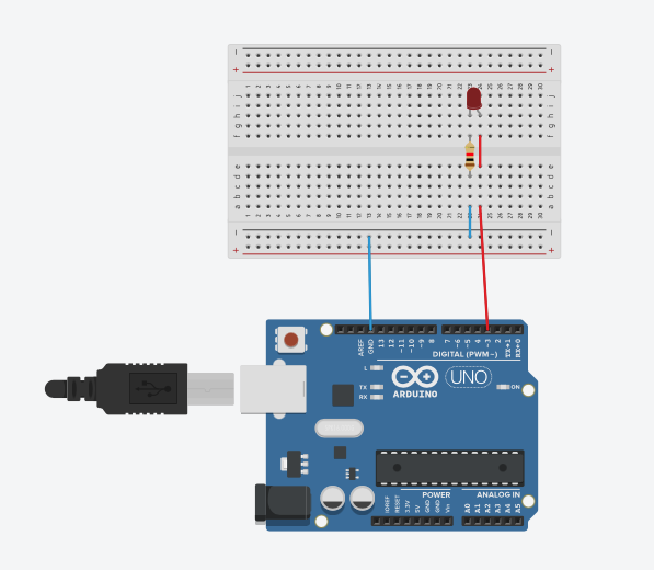
Extend previous circuit and add one more LED (green).

|
You can start with a toy problem: control two leds with the same timing of HIGH and LOW state:

|
or in short:
|
1 2 |
LED_RED: 1,1,1,1,1,... LED_GREEN: 1,1,1,1,1,... |
The code for this is simple:
|
1 2 3 4 5 6 7 8 9 10 11 12 13 14 15 16 17 18 |
#define LED_RED 3 #define LED_GREEN 2 void setup() { pinMode(LED_RED, OUTPUT); pinMode(LED_GREEN, OUTPUT); } void loop() { digitalWrite(LED_RED, HIGH); digitalWrite(LED_GREEN, HIGH); delay(1000); digitalWrite(LED_RED, LOW); digitalWrite(LED_GREEN, LOW); delay(1000); } |
Even if you have non-equal timing for on and off state, the problem is trivial because there is no need for real "concurrency" as both leds changes their state at the same time:

|
|
1 2 |
LED_RED: 2,1,2,1,2,... LED_GREEN: 2,1,2,1,2,... |
|
1 2 3 4 5 6 7 8 9 10 11 12 13 14 15 16 17 18 |
#define LED_RED 3 #define LED_GREEN 2 void setup() { pinMode(LED_RED, OUTPUT); pinMode(LED_GREEN, OUTPUT); } void loop() { digitalWrite(LED_RED, HIGH); digitalWrite(LED_GREEN, HIGH); delay(2000); digitalWrite(LED_RED, LOW); digitalWrite(LED_GREEN, LOW); delay(1000); } |
The problem becomes apparent, when timings for different object are different:
|
1 2 |
LED_RED: 1,1,1,1,1,... LED_GREEN: 1,2,1,2,1,... |
|
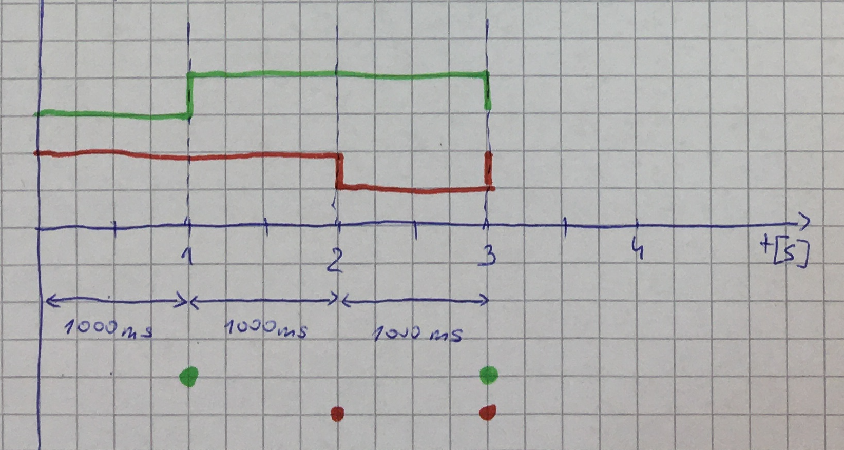
1 2 |
LED_RED: 1,2,1,2,1,... LED_GREEN: 2,1,2,1,2,... |
|
1 2 |
LED_RED: 1,1,1,1,1,... LED_GREEN: 0.5,0.75,0.5,0.75,0.5,0.75,... |
Second from the above cases are feasible:
|
|
1 2 3 4 5 6 7 8 9 10 11 12 13 14 15 16 17 18 19 20 21 22 23 24 25 26 |
#define LED_RED 4 #define LED_GREEN 3 void setup() { pinMode(LED_RED, OUTPUT); pinMode(LED_GREEN, OUTPUT); } void loop() { digitalWrite(LED_RED, HIGH); digitalWrite(LED_GREEN, LOW); delay(1000); //digitalWrite(LED_RED, HIGH); digitalWrite(LED_GREEN, HIGH); delay(1000); digitalWrite(LED_RED, LOW); //digitalWrite(LED_GREEN, HIGH); delay(1000); } |
The same but with shifted timing for green LED:

|
|
1 2 3 4 5 6 7 8 9 10 11 12 13 14 15 16 17 18 19 20 21 22 23 24 25 26 27 28 29 30 31 |
#define LED_RED 4 #define LED_GREEN 3 void setup() { pinMode(LED_RED, OUTPUT); pinMode(LED_GREEN, OUTPUT); } void loop() { digitalWrite(LED_RED, HIGH); digitalWrite(LED_GREEN, LOW); delay(500); //digitalWrite(LED_RED, HIGH); digitalWrite(LED_GREEN, HIGH); delay(1500); digitalWrite(LED_RED, LOW); //digitalWrite(LED_GREEN, HIGH); delay(500); //digitalWrite(LED_RED, HIGH); digitalWrite(LED_GREEN, LOW); delay(500); } |
The disadvantage of this solution is that every delay affects both leds and it may be difficult to control them independently. It may happened that changing timing of one led will force you to change code drastically. In more complex dependencies it may be difficult to find "cycle" -- repeatable pattern you can hardcode:

|
|
1 2 3 4 5 6 7 8 9 10 11 12 13 14 15 16 17 18 19 20 21 22 23 24 25 26 27 28 29 30 31 32 33 34 35 |
#define LED_RED 3 #define LED_GREEN 2 void setup() { pinMode(LED_RED, OUTPUT); pinMode(LED_GREEN, OUTPUT); } void loop() { digitalWrite(LED_RED, HIGH); digitalWrite(LED_GREEN, HIGH); delay(1000); digitalWrite(LED_RED, LOW); //digitalWrite(LED_GREEN, HIGH); delay(1000); digitalWrite(LED_RED, HIGH); digitalWrite(LED_GREEN, LOW); delay(1000); digitalWrite(LED_RED, LOW); digitalWrite(LED_GREEN, HIGH); delay(1000); digitalWrite(LED_RED, HIGH); //digitalWrite(LED_GREEN, HIGH); delay(1000); digitalWrite(LED_RED, LOW); digitalWrite(LED_GREEN, LOW); delay(1000); } |
delay and counterNow you will see better approach allowing you to control independently (almost) as many objects as you want.
You will use very short delay to avoid blocking and count how many will happen. If you reach a given number of calls, you will take an action.
To make things simpler, start with equal timing for on and off state with only one led:
|
1 2 3 4 5 6 7 8 9 10 11 12 13 14 15 16 17 18 19 20 21 22 23 24 25 26 27 28 29 30 31 |
#define LED_RED 3 int counterRed = 0; char stateLedRed = LOW; void setup() { pinMode(LED_RED, OUTPUT); } void toogleLedRed() { if (stateLedRed == LOW) { stateLedRed = HIGH; } else { stateLedRed = LOW; } digitalWrite(LED_RED, stateLedRed); } void loop() { if (counterRed == 100) { counterRed = 0; toogleLedRed(); } delay(10); counterRed++; } |
Now you can extend the previous case to non-equal timing for on and off state:
|
1 2 3 4 5 6 7 8 9 10 11 12 13 14 15 16 17 18 19 20 21 22 23 24 25 26 27 28 29 30 31 32 33 34 35 36 37 38 39 |
#define LED_RED 3 int counterRedOn = 0; int counterRedOff = 0; char stateLedRed = LOW; void setup() { pinMode(LED_RED, OUTPUT); } void toogleRed() { if (stateLedRed == LOW) { stateLedRed = HIGH; } else { stateLedRed = LOW; } digitalWrite(LED_RED, stateLedRed); } void loop() { if ((stateLedRed == HIGH) && (counterRedOn == 200)) { counterRedOn = 0; toogleLedRed(); } else if ((stateLedRed == LOW) && (counterRedOff == 100)) { counterRedOff = 0; toogleLedRed(); } delay(10); if (stateLedRed == LOW) { counterRedOff++; } else { counterRedOn++; } } |
Because counterRedOff and counterRedOn are increased inclusively (either counterRedOff or counterRedOn) you can use one counter as it is showed bellow:
|
1 2 3 4 5 6 7 8 9 10 11 12 13 14 15 16 17 18 19 20 21 22 23 24 25 26 27 28 29 30 31 32 33 34 35 36 37 |
#define LED_GREEN 2 #define LED_RED 3 int counterRed = 0; char stateLedRed = LOW; void setup() { pinMode(LED_GREEN, OUTPUT); pinMode(LED_RED, OUTPUT); } void toogleRed() { if (stateLedRed == LOW) { stateLedRed = HIGH; } else { stateLedRed = LOW; } digitalWrite(LED_RED, stateLedRed); } void loop() { if ((stateLedRed == HIGH) && (counterRed == 100)) { counterRed = 0; toogleRed(); } else if ((stateLedRed == LOW) && (counterRed == 200)) { counterRed = 0; toogleRed(); } delay(10); counterRed++; } |
Finally you can adopt this approach to non-equal timing for on and off state of two leds.
|
1 2 3 4 5 6 7 8 9 10 11 12 13 14 15 16 17 18 19 20 21 22 23 24 25 26 27 28 29 30 31 32 33 34 35 36 37 38 39 40 41 42 43 44 45 46 47 48 49 50 51 52 53 54 55 56 57 |
#define LED_GREEN 2 #define LED_RED 3 int counterRed = 0; int counterGreen = 0; char stateLedRed = LOW; char stateLedGreen = LOW; void setup() { pinMode(LED_GREEN, OUTPUT); pinMode(LED_RED, OUTPUT); } void toogleRed() { if (stateLedRed == LOW) { stateLedRed = HIGH; } else { stateLedRed = LOW; } digitalWrite(LED_RED, stateLedRed); } void toogleGreen() { if (stateLedGreen == LOW) { stateLedGreen = HIGH; } else { stateLedGreen = LOW; } digitalWrite(LED_GREEN, stateLedGreen); } void loop() { if ((stateLedRed == HIGH) && (counterRed == 200)) { counterRed = 0; toogleRed(); } else if ((stateLedRed == LOW) && (counterRed == 100)) { counterRed = 0; toogleRed(); } if ((stateLedGreen == HIGH) && (counterGreen == 50)) { counterGreen = 0; toogleGreen(); } else if ((stateLedGreen == LOW) && (counterGreen == 250)) { counterGreen = 0; toogleGreen(); } delay(10); counterRed++; counterGreen++; } |
Problems with this improvement:
Lack of control over code "outside" delay -- it may take as much time as it want and delay will have no idea how much time elapsed between two subsequent calls. It means that you have to "collect" 100 delay(10)s regardless of the time passed between every two delay(10)s. In consequence 100*delay(10) is not equal to delay(1000). It wouldn't be less but it may be (much) more.
millis() functionThe problem with previous solution is that sometimes
90*delay(10)+T would be equal to delay(1000) or next time 98*delay(10)+T would be equal to delay(1000), where T is an extra (non-constant, unpredictable) time microcontroller needs to complete some task(s) between every two delay(10)s
That's why thing you are looking for is rather a variable counter increment, something of the following form:
|
1 2 3 4 5 6 7 |
[...] delay(10); counterRed += increment according to real time passage; sometimes by 1 as you did so far, sometimes by 3 or 5 or anything related to real time [...] |
Non-blocking equal timing for on and off state.
|
1 2 3 4 5 6 7 8 9 10 11 12 13 14 15 16 17 18 19 20 21 22 23 24 25 26 27 28 29 30 31 32 33 34 35 |
#define LED_RED 3 #define INTERVAL_RED 1000 char stateLedRed = LOW; unsigned long counterRed = 0; unsigned long counterCurrent; unsigned long increment; void setup() { pinMode(LED_RED, OUTPUT); } void toogleRed() { if (stateLedRed == LOW) { stateLedRed = HIGH; } else { stateLedRed = LOW; } digitalWrite(LED_RED, stateLedRed); } void loop() { if (counterRed > INTERVAL_RED) { toogleRed(); counterRed = 0; } counterCurrent = millis(); increment = counterCurrent - counterRed; counterRed = counterCurrent; counterRed += increment; } |
In most cases this is implemented as below:
|
1 2 3 4 5 6 7 8 9 10 11 12 13 14 15 16 17 18 19 20 21 22 23 24 25 26 27 28 29 30 31 32 33 |
#define LED_RED 3 #define INTERVAL_RED 1000 char stateLedRed = LOW; unsigned long counterRed = 0; unsigned long counterCurrent; void setup() { pinMode(LED_RED, OUTPUT); } void toogleRed() { if (stateLedRed == LOW) { stateLedRed = HIGH; } else { stateLedRed = LOW; } digitalWrite(LED_RED, stateLedRed); } void loop() { currentCounter = millis(); if (counterCurrent - counterRed > INTERVAL_RED) { counterRed = counterCurrent; toogleRed(); } } |
In the above solution you still count something (number of milliseconds from starting/reseting your microcontroller) but this process of counting depends on time. In most cases instead of counter you will use different names -- below you have the same code as above but with different names for variables:
|
1 2 3 4 5 6 7 8 9 10 11 12 13 14 15 16 17 18 19 20 21 22 23 24 25 26 27 28 29 30 31 32 33 |
#define LED_RED 3 #define INTERVAL_RED 1000 char stateLedRed = LOW; unsigned long previousMillis = 0; unsigned long currentMillis; void setup() { pinMode(LED_RED, OUTPUT); } void toogleRed() { if (stateLedRed == LOW) { stateLedRed = HIGH; } else { stateLedRed = LOW; } digitalWrite(LED_RED, stateLedRed); } void loop() { currentMillis = millis(); if (currentMillis - previousMillis > INTERVAL_RED) { previousMillis = currentMillis; toogleRed(); } } |
Adopting this approach to non-blocking non-equal timing for on and off state is quite easy:
|
1 2 3 4 5 6 7 8 9 10 11 12 13 14 15 16 17 18 19 20 21 22 23 24 25 26 27 28 29 30 31 32 33 34 35 36 37 38 |
#define LED_RED 3 #define INTERVAL_RED_ON 2000 #define INTERVAL_RED_OFF 1000 char stateLedRed = LOW; unsigned long previousMillis = 0; unsigned long currentMillis; void setup() { pinMode(LED_RED, OUTPUT); } void toogleRed() { if (stateLedRed == LOW) { stateLedRed = HIGH; } else { stateLedRed = LOW; } digitalWrite(LED_RED, stateLedRed); } void loop() { currentMillis = millis(); if ((stateLedRed == HIGH) && (currentMillis - previousMillis > INTERVAL_RED_ON)) { previousMillis = currentMillis; toogleRed(); } else if ((stateLedRed == LOW) && (currentMillis - previousMillis > INTERVAL_RED_OFF)) { previousMillis = currentMillis; toogleRed(); } } |
Non-blocking non-equal timing for on and off state of two different LEDs.
|
1 2 3 4 5 6 7 8 9 10 11 12 13 14 15 16 17 18 19 20 21 22 23 24 25 26 27 28 29 30 31 32 33 34 35 36 37 38 39 40 41 42 43 44 45 46 47 48 49 50 51 52 53 54 55 56 57 58 59 60 61 62 63 64 65 |
#define LED_GREEN 2 #define LED_RED 3 #define INTERVAL_RED_ON 2000 #define INTERVAL_RED_OFF 1000 #define INTERVAL_GREEN_ON 500 #define INTERVAL_GREEN_OFF 2500 char stateLedRed = LOW; char stateLedGreen = LOW; unsigned long previousMillisLedRed = 0; unsigned long previousMillisLedGreen = 0; unsigned long currentMillis; void setup() { pinMode(LED_GREEN, OUTPUT); pinMode(LED_RED, OUTPUT); } void toogleRed() { if (stateLedRed == LOW) { stateLedRed = HIGH; } else { stateLedRed = LOW; } digitalWrite(LED_RED, stateLedRed); } void toogleGreen() { if (stateLedGreen == LOW) { stateLedGreen = HIGH; } else { stateLedGreen = LOW; } digitalWrite(LED_GREEN, stateLedGreen); } void loop() { currentMillis = millis(); if ((stateLedRed == HIGH) && (currentMillis - previousMillisLedRed > INTERVAL_RED_ON)) { previousMillisLedRed = currentMillis; toogleRed(); } else if ((stateLedRed == LOW) && (currentMillis - previousMillisLedRed > INTERVAL_RED_OFF)) { previousMillisLedRed = currentMillis; toogleRed(); } if ((stateLedGreen == HIGH) && (currentMillis - previousMillisLedGreen > INTERVAL_GREEN_ON)) { previousMillisLedGreen = currentMillis; toogleGreen(); } else if ((stateLedGreen == LOW) && (currentMillis - previousMillisLedGreen > INTERVAL_GREEN_OFF)) { previousMillisLedGreen = currentMillis; toogleGreen(); } } |
Add button to the previous circuit:

|
Upload to microcontroller the following code to switch on and off red LED:
|
1 2 3 4 5 6 7 8 9 10 11 12 13 14 15 16 17 18 19 20 21 22 23 24 25 26 27 28 29 30 |
#define BUTTON 8 #define LED_RED 3 int stateLedRed = LOW; void setup() { pinMode(LED_RED, OUTPUT); pinMode(BUTTON, INPUT); } void toogleLedRed() { if (stateLedRed == LOW) { stateLedRed = HIGH; } else { stateLedRed = LOW; } digitalWrite(LED_RED, stateLedRed); } void loop() { if (digitalRead(BUTTON) == HIGH) { delay(20); toogleLedRed(); while(digitalRead(BUTTON) == HIGH); delay(20); } } |
To simulate time-consuming task add delay(10000):
|
1 2 3 4 5 6 7 8 9 10 11 12 13 14 15 16 17 18 19 20 21 22 23 24 25 26 27 28 29 30 31 32 |
#define BUTTON 8 #define LED_RED 3 int stateLedRed = LOW; void setup() { pinMode(LED_RED, OUTPUT); pinMode(BUTTON, INPUT); } void toogleLedRed() { if (stateLedRed == LOW) { stateLedRed = HIGH; } else { stateLedRed = LOW; } digitalWrite(LED_RED, stateLedRed); } void loop() { if (digitalRead(BUTTON) == HIGH) { delay(20); toogleLedRed(); while(digitalRead(BUTTON) == HIGH); delay(20); } delay(10000); } |
As you can see, now it's almost impossible to switch LED. If you are lucky, you can do this only in short time-slots between delay(10000)s.
Interrupt, as it name states, interrupt the current work of microcontroller such that some other work can be done. What is important, it does not stop or break other activity but only interrupts it. After completion, microcontroller return back to interrupted job.
To understand this consider the following simple story:
Suppose you are sitting at home, chatting with someone (current work). Suddenly the telephone rings (interrupt occurs). You stop chatting, and pick up the telephone to speak to the caller (the interrupt service routine is called). When you have finished your telephonic conversation, you go back to chatting with the person before the telephone rang (return back to interrupted job).
Here are some important features about interrupts:
- Interrupts can come from various sources:
- Hardware external source Microcontroller uses a hardware interrupt that is triggered by a state change on one of the digital pins.
- Hardware internal source Microcontroller uses a hardware interrupt that is triggered by a state change on one of the internal component -- very often timer or counter.
- Software source A software interrupt is requested by the processor itself upon executing particular instructions or when certain conditions are met. It may be intentionally caused by executing a special instruction which, by design, invokes an interrupt when executed. Such instructions function similarly to subroutine calls and are used for a variety of purposes, such as requesting operating system services and interacting with device drivers (e.g., to read or write storage media). Software interrupts may also be triggered by program execution errors or by the virtual memory system.
- Every software interrupt signal is associated with a particular interrupt handler.
- Microcontroller has dedicated pins to work with interrupts:
12345Uno, Nano, Mini, other 328-based: 2, 3Micro, Leonardo, other 32u4-based: 0, 1, 2, 3, 7Mega, Mega2560, MegaADK: 2, 3, 18, 19, 20, 21 (pins 20 & 21 are not available to usefor interrupts while they are usedfor I2C communication) - ISR (Interrupt Service Routine) is a common name for routine called when interrupt occurs.
- You define the routine and specify conditions related to interrupt occurrence: the rising edge, falling edge, change state etc.
- Generally, an ISR should be as short and fast as possible.
- You can mask an interrupt. Masking means disabling interrupt making it to be deferred or ignored by the processor. When the interrupt is disabled, the associated interrupt signal may be ignored by the processor, or it may remain pending. Signals which are affected by the mask are called maskable interrupts. Some interrupt signals are not affected by the interrupt mask and therefore cannot be disabled; these are called non-maskable interrupts (NMIs). These indicate high-priority events which cannot be ignored under any circumstances, such as the timeout signal from a watchdog timer.
- Interrupt is triggered by different "events" describing how the signal was changed:
- CHANGE -- runs functions on each change of the pin state.
- LOW -- runs the function if the chip pin is
LOW. - FALLING -- runs the function when the state changes from
HIGHtoLOW. - RISING -- runs functions when the state changes from
LOWtoHIGH.
A watchdog timer (sometimes called a computer operating properly or COP timer, or simply a watchdog) is an electronic or software timer that is used to detect and recover from computer malfunctions. Watchdog timers are widely used in computers to facilitate automatic correction of temporary hardware faults, and to prevent errant or malevolent software from disrupting system operation.
During normal operation, the computer regularly restarts the watchdog timer to prevent it from elapsing, or "timing out". If, due to a hardware fault or program error, the computer fails to restart the watchdog, the timer will elapse and generate a timeout signal. The timeout signal is used to initiate corrective actions. The corrective actions typically include placing the computer and associated hardware in a safe state and invoking a computer reboot.

|
|
1 2 3 4 5 6 7 8 9 10 11 12 13 14 15 16 17 18 19 20 21 22 23 24 25 26 27 28 29 30 31 32 33 34 35 |
#define BUTTON 3 #define LED_RED 4 int stateLedRed = LOW; void setup() { Serial.begin(9600); attachInterrupt(digitalPinToInterrupt(BUTTON), isrToControlLED, RISING); pinMode(LED_RED, OUTPUT); } void toogleLedRed() { if (stateLedRed == LOW) { stateLedRed = HIGH; } else { stateLedRed = LOW; } digitalWrite(LED_RED, stateLedRed); } void isrToControlLED() { if(digitalRead(BUTTON) == HIGH){ delay(20); toogleLedRed(); while(digitalRead(BUTTON) == HIGH); delay(20); } } void loop() { Serial.print(millis()/1000.0); delay(10000); } |
The code presented in previous section works in Tinkercad simulator but there is a question wether it is as it should be and you are allowed to use
delay inside ISR or not. Why you may have some doubts? Well, it may happened that clock is controlled by interrupt so when you are inside ISR to handle interrupt, clock interrupt may be blocked. If this is a case, delay may not be able to detect time passing and you will block forever you code inside ISR. Or maybe this statement is false, and everything works as expected?
Unfortunately an Internet with tones of blogs, vlogs and any other -logs doesn't help as you can find contradictory descriptions:
- From ARDUINO PROGRAMMING GUIDE SERIES Can You Use Delay() Inside Interrupt Service Routine?
A question I often receive is about the contents of the ISR:
"Can I include arbitrary code?"
"Can I include slow functions like delay() or even Serial.print()?"
Although this is possible, you should not.Conclusion: yes, you can.
- From Arduino delay inside of an Interrupt
The first problem is that delay() is a busy loop monitoring millis(). The value that millis() returns will not change inside an ISR as interrupts are turned off inside an ISR; this is why ISRs must be as short and fast as possible, or they will interfere with other interrupts.So if you call delay() within an ISR your poor AVR is now deadlocked! It is waiting for something to happen that can now never happen.
A second problem is that if your ISR takes too long, you can miss other interrupts; millis() and micros() can miss ticks and become inaccurate!
Conclusion: no, you can't.
Hmm... Now you can test it on your own on real device. In my case everything was working as expected.
Anyway, using delay every time blocks your microcontroller. You may say: Only for twenty milliseconds! Only? Let's test what microcontroller can do for you in this time. First prepare "testing environment":
|
1 2 3 4 5 6 7 8 9 10 11 12 13 14 15 16 17 18 19 20 21 22 23 24 |
int i = 1; unsigned long v = 2; void setup() { Serial.begin(9600); } void loop() { // START task unsigned long timeStart = millis(); while(true) { // DO SOMETHING HERE if (millis()-timeStart > 10) break; } unsigned long timeStop = millis(); // STOP task after 10 milliseconds Serial.println(timeStart); Serial.println(timeStop); Serial.println(i); delay(200000); } |
Now you can replace the line
|
1 |
// DO SOMETHING HERE |
with
|
1 |
i++; |
and run your code. In my case the following output was printed:
|
1 2 3 |
0 <- millis when you enter to test block 11 <- millis when you leave test block 5779 <- value of variable 'i' |
As you can see, in 10 milliseconds time slot my microcontroller was able to repeat for loop 5779 times!
When you replace the line
|
1 |
int i = 1; |
with
|
1 |
unsigned long i = 1; |
and run your code you will get different result:
|
1 2 3 |
0 11 4371 <- value of variable 'i' |
Notice that only because you change type for i from int to unsigned long my code slowed down from 5779 to 4371 iterations.
Now paste the line:
|
1 |
v *= 2; |
just after previously pasted:
|
1 |
i++; |
If I run this code, I got the following results:
|
1 2 3 |
0 11 2938 <- value of variable 'i' |
2938 is much lower than 5779 but it is still a lot of power to do many interesting tasks.
As you can see, it makes sense to implement ISR without delay inside (regardless of whether you can or cannot use delay inside ISR). Below I present my code:
|
1 2 3 4 5 6 7 8 9 10 11 12 13 14 15 16 17 18 19 20 21 22 23 24 25 26 27 28 29 30 31 32 33 34 35 36 37 38 39 |
#define BUTTON 2 #define LED_RED 13 int stateLedRed = LOW; int stateButton = LOW; unsigned long lastToogleTime = 0; void setup() { Serial.begin(9600); attachInterrupt(digitalPinToInterrupt(BUTTON), switchLed, CHANGE); pinMode(LED_RED, OUTPUT); digitalWrite(LED_RED, stateLedRed); } void toogleLedRed() { if (stateLedRed == LOW) { stateLedRed = HIGH; } else { stateLedRed = LOW; } digitalWrite(LED_RED, stateLedRed); } void switchLed() { unsigned long currentTime = millis(); if ((stateButton == LOW) && (currentTime-lastToogleTime > 20)) { toogleLedRed(); lastToogleTime = millis(); stateButton = HIGH; } else if ((stateButton == HIGH) && (currentTime-lastToogleTime > 20)) { lastToogleTime = millis(); stateButton = LOW; } } void loop() { Serial.println(millis()/1000.0); delay(10000); } |
With this code again you should be able to switch the state of your LED anytime you want but you don't use blocking delay.
By the way, as now you know interrupts, you can test switch bouncing described in tutorial Pull resistors. Upload the following code to your microcontroller:
|
1 2 3 4 5 6 7 8 9 10 11 12 13 14 15 16 |
#define BUTTON 2 int iRising = 0; void setup() { Serial.begin(9600); attachInterrupt(digitalPinToInterrupt(BUTTON), isr, RISING); } void isr() { iRising++; } void loop() { Serial.println(iRising); delay(1000); } |
If you press the button again and again you will notice some gaps as in my case:
|
1 2 3 4 5 6 7 8 9 10 11 12 13 14 15 16 17 18 19 20 21 22 23 24 25 26 27 28 29 30 31 32 |
0 [... CUT ...] 0 1 [... CUT ...] 1 2 [... CUT ...] 2 3 [... CUT ...] 3 4 [... CUT ...] 4 6 <-- GAP!! [... CUT ...] 6 8 <-- GAP!! [... CUT ...] 8 9 [... CUT ...] 9 10 [... CUT ...] 10 12 <-- GAP!! [... CUT ...] 12 14 <-- GAP!! [... CUT ...] |
The gaps are caused by spikes which appear in unstable membrane time when you press the button. When you press the button, you increase iRising by 1 and from time to time this variable is also increase by HIGH states of spikes.