
Published: 2022-01-03
Last update: 2023-06-20
In this tutorial you will learn how to get analog results with digital means. You will use digital control to create a square wave, a signal switched between ON and OFF. By changing the portion of the time the signal spends ON versus the time that the signal spends OFF your microcontroller can simulate any voltage in between the full operating voltage (e.g., 5 V on UNO, 3.3 V on a MKR board) and off (0 Volts).
Table of contents
I explain different type of microcontroller's pins in Different voltage level coexistence part. Please refer to section Type of pins if this topic is new for you or you don't remember this material.
One thing you should keep in mind is that in this part you will use only pure digital pins, that is the pins which can output only two levels of signal: either ON which is the full operating voltage Vcc dependent on the platform you use (e.g., 5 V on UNO, 3.3 V on a MKR board) corresponding to HIGH state or OFF (0 Volts), corresponding to LOW state.
Assembly simple circuit given below:

|
Next upload the following code:
|
1 2 3 4 5 6 7 8 9 10 11 12 13 |
#define PIN_LED 12 #define DELAY_TIME 1000 void setup() { pinMode(PIN_LED, OUTPUT); } void loop() { digitalWrite(PIN_LED, HIGH); delay(DELAY_TIME); digitalWrite(PIN_LED, LOW); delay(DELAY_TIME); } |
When you execute the code you will see the LED turning on and turning off with low rate (1000ms for each state). At the same time voltage observed on multimeter changes from LOW level to HIGH level and back:

|

|
Left: LED is turned off (LOW voltage level, close to 0V) Right: LED is turned on (HIGH voltage level, close to 5V) |
|
In this experiment you use the same circuit as before and almost the same code with tiny modification -- replace the line:
|
1 |
#define DELAY_TIME 1000 |
with the:
|
1 |
#define DELAY_TIME 1 |
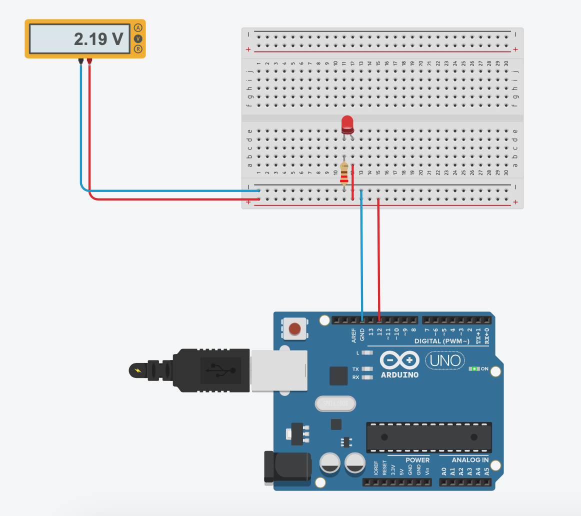
This way you obtain a high-speed LED switching (1ms for each state). Now voltage is very stable, around 2.2V:
|
You should expect voltage close to 2.5V:
|
1 2 3 4 5 |
h - length of HIGH state l - length of LOW state c - length of a whole cycle which is a sum of 'h' and 'l' (h/c) * 5V = (h/(h+l)) * 5V = (1/2) * 5V = 2.5V |
However, as you have seen in Experiment 1, HIGH voltage is not exactly 5V but rather 4.4V and hence the result:
|
1 |
1/2 * 4.5V = 2.2V |
Your LED shouldn't be so bright as before. To make it clear you can use circuit with two "reference" LEDs: one (most left) always turned off, and second (most right) always fully turned on:

|
In this experiment you will continue high speed switching approach but also try to change the portion of the time the signal spends ON versus the time that the signal spends OFF.
First change the code to the following form:
|
1 2 3 4 5 6 7 8 9 10 11 12 13 14 15 16 |
#define PIN_LED 12 #define DELAY_TIME_HIGH 1 #define DELAY_TIME_LOW 2 void setup() { pinMode(PIN_LED, OUTPUT); } void loop() { digitalWrite(PIN_LED, HIGH); delay(DELAY_TIME_HIGH); digitalWrite(PIN_LED, LOW); delay(DELAY_TIME_LOW); } |
Two constants DELAY_TIME_HIGH and DELAY_TIME_LOW allow you to control independently length of HIGH and LOW state.
Test three cases:
HIGH=1ms,LOW=2ms
Expected voltage is:
1234h - length of HIGH statel - length of LOW state(h/(h+l)) * 5V = (1/(1+2)) * 5V = 1.66V
Taking into account that voltage is rather 4.4V than 5V, expected result is:
11/3 * 4.4V = 1.46V

- Now "reverse" proportions and set
HIGH=2msandLOW=1ms. For these assumptions you will obtain:
1234h - length of HIGH statel - length of LOW state(h/(h+l)) * 4.4V = (2/(2+1)) * 4.4V = 2.93V

- And finally make a test for
HIGH=1ms,LOW=9ms:
1234h - length of HIGH statel - length of LOW state(h/(h+l)) * 4.4V = (1/(1+9)) * 4.4V = 0.44V = 450mV


This experiment requires you to add potentiometer to use analog signal to control LED brightness by changing proportions between the length of
HIGH and LOW state without the need of programming microcontroller again and again:

|
- Visible flickering
Use the following code:
1234567891011121314151617#define PIN_LED 12#define PIN_POTENTIOMETER A0#define DELAY_TIME_HIGH 1void setup() {pinMode(PIN_LED, OUTPUT);}void loop() {int brightness = analogRead(PIN_POTENTIOMETER);brightness = (int)(brightness * (35.0 / 1023.0));digitalWrite(PIN_LED, HIGH);delay(DELAY_TIME_HIGH);digitalWrite(PIN_LED, LOW);delay(brightness);}
The formula:
1brightness = (int)(brightness * (35.0 / 1023.0));
computesbrightnessto be in range from 0 to 35.With the above code you can control brightness but you will see visible and annoying flickering.
- Visible flickering for selected value
Using the code from previous experiment note valueBofbrightnessfor which you obtain the most visible flickering. In my case it wasB=35. Please note that the best results you will have with real hardware and I strongly encourage you to use it instead of simulation in for example Tinkercad.Substitute this value instead of
brightnessand modify the code (at this moment potentiometer is not needed):12345678910111213#define PIN_LED 12#define DELAY_TIME_HIGH 1void setup() {pinMode(PIN_LED, OUTPUT);}void loop() {digitalWrite(PIN_LED, HIGH);delay(DELAY_TIME_HIGH);digitalWrite(PIN_LED, LOW);delay(35);} - Keep the same proportion but make the whole cycle shorter
From previous experiment you know the worse case forbrightness. Now you take flickering code you used there and, preserving ratio ofHIGHtoLOWstate which is equal to 1/B as well as cycle time which is equal to 1+B, you change (decrease) time unit from milliseconds to microseconds (1 second [s] = 1000 milliseconds [ms]; 1 milliseconds = 1000 microseconds [us]):12345678910111213#define PIN_LED 12#define DELAY_TIME 1void setup() {pinMode(PIN_LED, OUTPUT);}void loop() {digitalWrite(PIN_LED, HIGH);delayMicroseconds(DELAY_TIME_HIGH);digitalWrite(PIN_LED, LOW);delayMicroseconds(35);}Now some magic happens. Ratio of
HIGHtoLOWis the same but because of different time unit (much shorter) flickering is not visible. Of course it doesn't mean that flickering doesn't exist. It is present all the time but for our eyes it is not noticeable. - Final step: full control of brightness without flickering thanks to using shorter cycles
With the following code:1234567891011121314151617#define PIN_LED 12#define PIN_POTENTIOMETER A0void setup() {pinMode(PIN_LED, OUTPUT);}void loop() {int brightness = analogRead(PIN_POTENTIOMETER);int vH = brightness;int vL = 1023-brightness;digitalWrite(PIN_LED,HIGH);delayMicroseconds(vH);digitalWrite(PIN_LED,LOW);delayMicroseconds(vL);}you get full control of brightness without flickering thanks to using shorter cycles.
The proportion between HIGH state and LOW state is important as it decide about (averaged) output voltage. All timings given below have the same proportion:
|
1 2 3 4 5 6 7 8 9 10 11 |
HIGH = 1000 LOW = 1000 proportion = 1/1 HIGH = 100 LOW = 100 proportion = 1/1 HIGH = 1 LOW = 1 proportion = 1/1 |
but, as you have seen in experiments, output voltage was the most stable in the last case, where total time of one HIGH+LOW cycle was the shortest.
In consequence, you can say that both proportion and length of time window (total time of one cycle) is important.
The duration of ON time is called the pulse width. To get varying analog values, you change (sometimes we say modulate) that pulse width. As you saw, if you apply this pulse width on-off pattern and repeat fast enough, the result is as if the signal is a steady voltage between 0 and Vcc -- you obtain approximated analog value. But still you operate with a square wave, taking only HIGH and LOW value. Averaging these values through time gives approximated analog voltage between 0 and Vcc.
The ratio of time a circuit or load is ON compared to the time the circuit or load is OFF is called duty cycle (sometimes called also duty factor) and is expressed as a percentage of ON time.
Approach examined so far has one undeniable advantage -- you can apply it to any digital output pin. In addition, you have full control on the duty cycle and frequency, however to be honest, it may be quite difficult to determine the appropriate constants for a particular duty cycle and frequency.
The most important disadvantage is that you can't leave the output running with the predefined duty cycle and frequency while the processor does something else.
Because the underlying mechanism is rather simple, the best option would be to have dedicated circuit inside microcontroller to make automatic hardware control on timing for ON and OFF state on a predefined pin. And this is exactly for what PWM (Pulse Width Modulation) exists.
In the Arduino's ecosystem to use PWM you simply call analogWrite(pin, dutyCycle), where dutyCycle is a value from 0 to 255, and pin is one of the PWM pins, because not all digital pins can be controlled by hardware. Often you recognize PWM pins thanks to tilde sign ~ preceding pin number:

|
The analogWrite() function provides a simple interface to the hardware PWM, but doesn't provide any control over frequency. To fully control PWM you have to dive into more technical details -- please read my XXX tutorial, if you are interested in this topic.
Note that analogWrite() function name is misleading as the output is a pure digital signal, often referred to as a square wave, taking only HIGH and LOW value. Averaging is what gives this signal the character of an analog signal between 0 and Vcc.
analogWrite() function usage is very simply -- see the following example:
|
1 2 3 4 5 6 7 8 9 10 11 |
#define PIN_LED 11 double percentage = 0; void setup() { pinMode(PIN_LED, OUTPUT); analogWrite(PIN_LED, (int)((255.0 * percentage)/100.0)); } void loop() { } |
Be aware of one detail: you must use PWM pin, for example pin number 11 in Arduino UNO.

|

|
| Left: 100% duty cycle (always ON) Right: 50% duty cycle (ON half of the time) | |

|

|
| Left: 20% duty cycle Right: 0% duty cycle (always OFF) | |
- Applications 1: LED
With hardware PWM LED brightness control becomes trivial tasks. Use the following circuit and the code given below:

123456789101112131415161718#define PIN_LED 11#define PIN_POTENTIOMETER A0double percentage = 0;int potentiometer = 0;void setup() {pinMode(PIN_LED, OUTPUT);}void loop() {potentiometer = analogRead(PIN_POTENTIOMETER);percentage = map(potentiometer, 0, 1023, 0, 100);percentage = constrain(percentage, 0, 100);analogWrite(PIN_LED, (int)((255.0 * percentage)/100.0));} - Application 2: control RGB LED
You can use a similar approach to control color of RGB LED; each component is controlled by dedicated PWM pin.You can apply one of the following codes to your RGB LED:
1234567891011121314151617181920212223#define PIN_LED_RED 11#define PIN_LED_GREEN 10#define PIN_LED_BLUE 9double percentage = 0.0;void setup(){pinMode(PIN_LED_RED, OUTPUT);pinMode(PIN_LED_GREEN, OUTPUT);pinMode(PIN_LED_BLUE, OUTPUT);}void loop(){percentage = random(0, 100);analogWrite(PIN_LED_RED, (int)((255.0 * percentage)/100.0));percentage = random(0, 100);analogWrite(PIN_LED_GREEN, (int)((255.0 * percentage)/100.0));percentage = random(0, 100);analogWrite(PIN_LED_BLUE, (int)((255.0 * percentage)/100.0));delay(500);}123456789101112131415161718192021222324252627#define PIN_LED_RED 11#define PIN_LED_GREEN 10#define PIN_LED_BLUE 9int r, g, b;void setup(){pinMode(PIN_LED_RED, OUTPUT);pinMode(PIN_LED_GREEN, OUTPUT);pinMode(PIN_LED_BLUE, OUTPUT);}void loop(){for (r=0; r<255; r += 10) {for (g=0; g<255; g += 10) {for (b=0; b<255; b += 10) {analogWrite(PIN_LED_RED, r);analogWrite(PIN_LED_GREEN, g);analogWrite(PIN_LED_BLUE, b);delay(25);}}}} - Application 3: servo
Also servos are controlled with PWM signal; you do this exactly the same way as you do for LED. Please try it on your own. More about servos you can find in my tutorial XXX.
