
In this tutorial you will learn what differs analog pin from digital and how to combine multiple devices when different voltage levels for power and communications are needed.
Table of contents
- Background of the problem
- Two devices powered with different voltage levels
- Send logic signals from 3.3V device to 5V device
- Send logic signals from 5V device to 3.3V device
- Bi-directional communication
- Example
Every microcontroller has multiple pins and they fulfill various roles but you can group them into three categories:
- power pins,
- analog pins,
- digital pins.

|

|
In case of Arduino, the power pins are as follows:
- Vin. The input voltage to the Arduino/Genuino board when it's using an external power source (as opposed to 5 volts from the USB connection or other regulated power source). You can supply voltage through this pin, or, if supplying voltage via the power jack, access it through this pin.
- 5V.This pin outputs a regulated 5V from the regulator on the board. The board can be supplied with power either from the DC power jack (7 - 12V), the USB connector (5V), or the VIN pin of the board (7-12V). Supplying voltage via the 5V or 3.3V pins bypasses the regulator, and can damage your board. We don't advise it.
- 3V3. A 3.3 volt supply generated by the on-board regulator. Maximum current draw is 50 mA.
- GND. Ground pins.
- IOREF. This pin on the Arduino/Genuino board provides the voltage reference with which the microcontroller operates. A properly configured shield can read the IOREF pin voltage and select the appropriate power source or enable voltage translators on the outputs to work with the 5V or 3.3V.
Digital pin reads voltage from a given range and transforms it to a set of only two possible values: HIGH and LOW logic state. For example, in Arduino Uno input voltage from range [0, 5] volts is transformed to a value HIGH for input voltage equal to 5V and to LOW for 0V. Being more precise, voltage close to 5V is transformed to HIGH and voltage close to 0V is transformed to LOW. In consequence , you have a following relationship:
| Voltage range | Logic level | Logic value |
|---|---|---|
| [0,0+l] | LOW | 0, false |
| [5-h, 5] | HIGH | 1, true |
In my tutorial dedicated to voltage dividers entitled Potentiometer you can read how you can find values $l$ and $h$ to determine ranges when voltage is treated as HIGH or LOW state.
Analog pin reads voltage from a given range and transforms it to a number, in most cases an integer from a given range. For example, in Arduino input voltage from range [0, 5] volts is transformed to an integer from range [0, 1023]. In consequence, analog pins read continuous signal (analog) but returns a limited number of different values (1024).
Sometimes, even if you can only read from an analog pin, you can also choose to use it as a typical digital pin (but the opposite is not true) -- check documentation or pinout of your microcontroller (for Arduino Uno you can use this way any pin from A0 to A5).
To use an analog pin as a digital pin, you simply have to set the mode for the pin, as you would do for digital pins in the setup() function. Then, you can use the digitalWrite() and digitalRead() functions as you do for pure digital pins.
Keep in mind that pin A4 works also as SDA pin, while A5 works as SCL pin when you use I2C bus.
You should separate two aspects of voltages used by electronic devices:
- One voltage level is used to power electronic device.
- At the same time it may happend that your electronic device communicates with other devices using different voltage level, named logic level.
As you can see on the back side of HC-05 module, it uses 5V as a main power voltage while 3.3V to communicate (pins RX and TX).

|

|
| Left image: HC-05 -- front side. Right image: HC-05 -- back side. | |
In consequence you may face the following problems (or their mixture):
- You use two devices powered with two different voltage levels, for example 5V and 3.3V.
- You send logic signals from device where 3.3V = HIGH to device where 5V = HIGH (sending data on one wire from lower logic level to higher logic level).
- You send logic signals from device where 5V = HIGH to device where 3.3V = HIGH (sending data on one wire from higher logic level to lower logic level).
- You send logic signals from/device where 3.3V = HIGH to/from device where 5V = HIGH (bi-directional communication on the same wires).

|
Let's discuss all of them.
Fortunately there is a very simple solution to our problem. You can use linear voltage regulator, switching converter or use a voltage divider as it is described in my Power tutorial.
Although voltage divider is widely used in many home made application and works quite well you have to remember that the current and voltage across divider produce power, which is dissipated in the form of heat. If that power exceeds the rating of the resistor, the heat begins to become a major problem and potentially may destroy resistor. Another aspect is efficiency or rather inefficiency of a voltage-divider-power-supply. The preferred solution, if you need to drop down a voltage to use it as a power supply, is a voltage regulator or switching converter.
In most cases this is not a problem, because 3.3V is accepted as a HIGH level for 5V logic level devices. As you know from preceding part, this is possible because to HIGH state is mapped any voltage from interval [5-h,5] volts where in most cases $h$ is big enough so the value 3.3 is in this range. If for some reason case would be different and our 5V device doesn't accept 3.3V as a HIGH level, look into further solutions.
This case is a little bit difficult. Solution seems to be simple: we can use a voltage divider. We will not dive into details about voltage divider here and give only a sample solution to give an idea. For details look into Voltage divider tutorial.

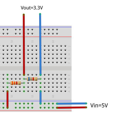
Generally speaking, formula used to calculate $V_{out}$ takes a form
$$V_{out} = \frac{V_{in}R_{2}}{R_{1}+R_{2}}$$
Be careful: I have found some cases when this approach doesn't work. I didn't have time to investigate this but my theory is that this might be a case for high speed communication (high sped switching from one logic state to other).
Todo (id=voltage_level_coexistence:voltage_divider_speed_test): Voltage divider speed test
In such a case we can use ready to use (bi-directional) logic level converter (see next section).
The real problem is when on the same wire sometimes we want send some data but other time receive them. In such a case a bi-directional logic level converter (BD-LLC for short) would be very helpful.


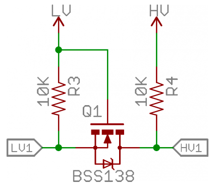
From technical point of view BD-LLC is a very simple device. There is basically one level-shifting circuit on the board, which is repeated four times to create four level-shifting channels. The circuit uses a single N-channel MOSFET (with internal Drain – Substrate Diode) and a couple pull-up resistors to realize bi-directional level shifting. Below there is one the bi-directional level-shifting circuit used on all four channels of the Sparkfun BD-LLC:
|
| The one bi-directional level-shifting circuit used on all four channels of the Sparkfun BD-LLC |
Explaining how logic level converter works is quite simple but to fully understand this part you may need to read and understand first materials related to:
Feel free to skip this part and return here when you will be ready.
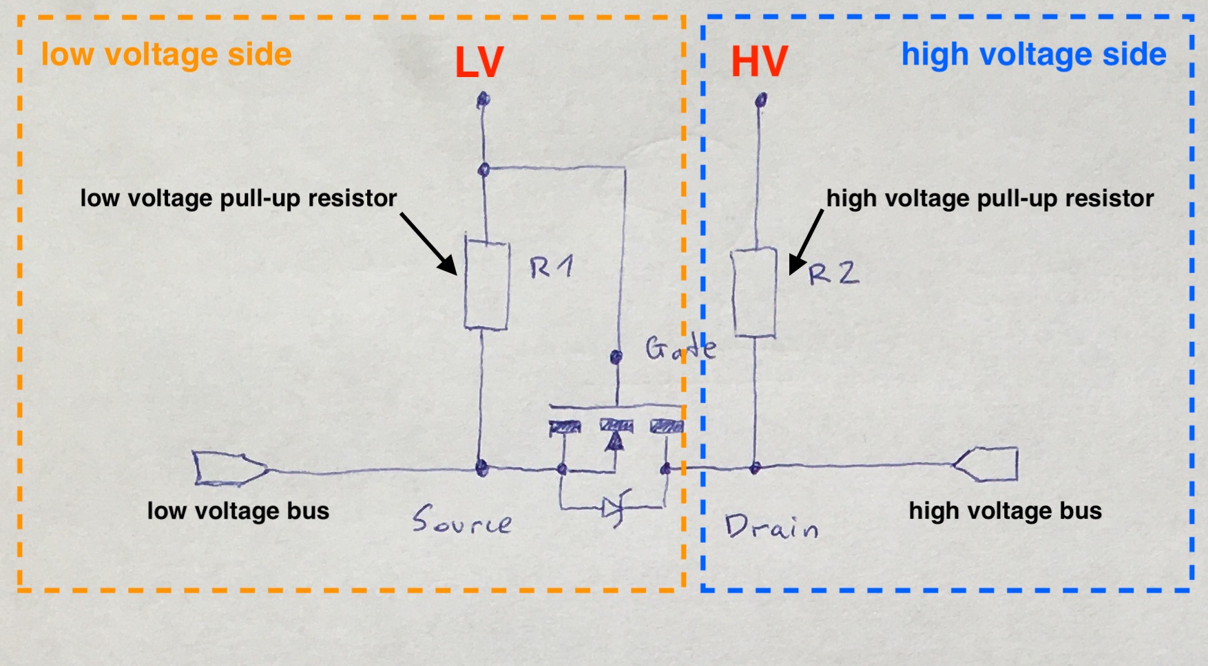
To make things simpler let me introduce some naming conventions and divide the circuit into two parts: the left side or the low voltage side and the right side or the high voltage side:
|
Moreover assume that LV=3.3V and HV=5.0V.
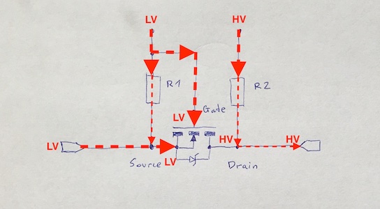
- Case 1: HIGH state from LOW logic level to HIGH logic level
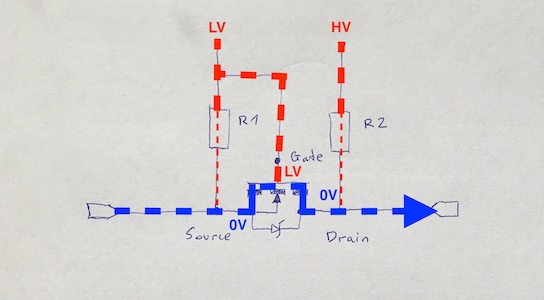
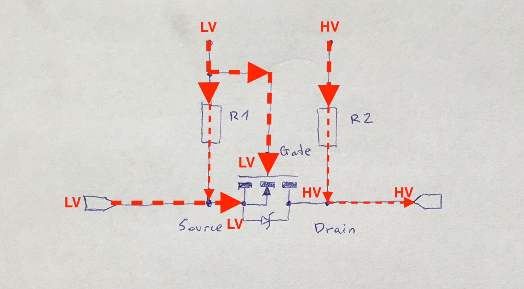
In this case neither devices i.e., device on low voltage side nor device on high voltage side is pulling the bus low (transmits LOW signal). The low voltage bus is either intentionally in HIGH state by providing directly to it 3.3V or it is pulled up "by default" by the low voltage pull-up resistors to low 3.3 voltage. Thus you have HIGH logic state on the low voltage side.As both the Gate and Source of the MOSFET are connected to 3.3V, the MOSFET’s Gate/Source voltage (VGS is 0V) is below the threshold voltage of the MOSFET. As a result, the MOSFET is not conducting and this allows the high voltage bus to be pulled high to 5V.
So, in this state, both sides of the bus are at logic HIGH but at different voltage levels. The situation may change only when one of data lines would be pulled down. That is why above reasoning also works in case of transmission HIGH state from high logic level to low logic level side.
- Case 2: HIGH state from HIGH logic level to LOW logic level
See explanation in case 1: HIGH state from LOW logic level to HIGH logic level.Again, if neither devices is pulling the bus low (transmits LOW signal) then both sides of the bus, "by default", are at logic HIGH but at different voltage levels.
- Case 3: LOW state from LOW logic level to HIGH logic level
When the low voltage device pulls down the bus line to LOW logic level, the Gate of the MOSFET is still at 3.3V but the Source becomes low. As a result, the VGS rises above the threshold, the MOSFET starts to conduct and the bus line at the MOSFET’s Drain is now pulled down as well.Hence, both sides of the bus are at LOW logic level (of same voltage level).
- Case 4: LOW state from HIGH logic level to LOW logic level
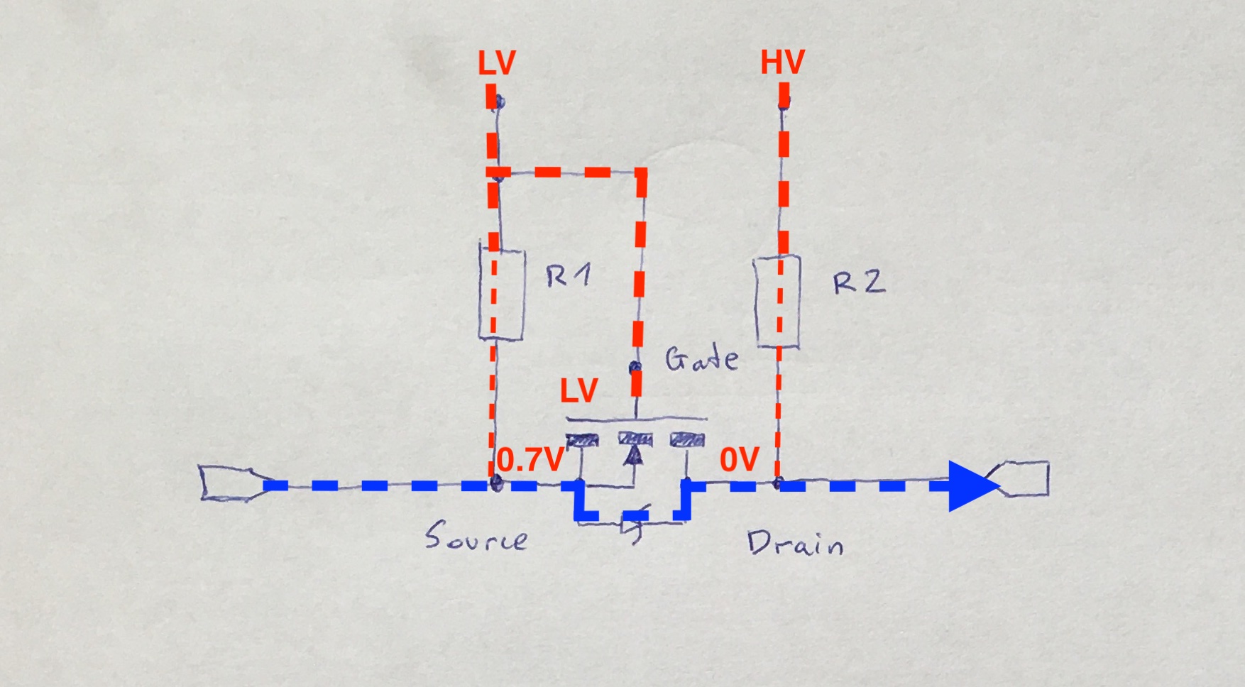
When the high voltage device pulls down the bus line to LOW logic level, at the MOSFET’s Drain, the MOSFET’s substrate diode allows the Source to also be partially pulled down due to a small amount of voltage dropped across the diode.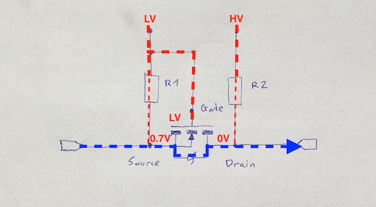
Next, because the MOSFET’s Source is partially pulled down, the VGS rises above the threshold and the MOSFET starts to conduct effectively bypassing the substrate diode.

In consequence both sides of the bus are at LOW logic level.


You can make your own logic level converter based on the above schema if you want. Instead of BSS138 and two 10kOhms resistors you can use BS170 accompanied with any two resistors between 1kOhm to 10kOhms since they acts only as pull up resistors.
There is also another equivalent circuit where instead of N-Channel MOSFET with internal diode you use bipolar transistor:

|
Let's take a closer look into pinouts of a Sparkfun BD-LLC. The smallest version of the Sparkfun BD-LLC which has 12 total pins – six headers arranged in two rows. One row contains all of the high voltage (e.g. 5V) inputs and outputs, the other row has all things low voltage (e.g. 3.3V).

To make things simple, the pins are labeled on both sides of the board, and organized into groups.
The pins labeled HV, LV, and two GND’s provide high and low voltage references to the board. Supplying a steady, regulated voltage to both of these inputs is required.
There are four separate data channels on this BD-LLC, each capable of shifting data to and from high and low voltages. These pins are labeled HV1, LV1, HV2, LV2, HV3, LV3, HV4, and LV4. The number at the end of each label designates the channel of the pin, and the HV or LV prefix determines whether it’s on the high or low side of the channel. Quite logic, isn't it?
A low-voltage signal sent in to LV1, for example, will be shifted up to the higher voltage and sent out HV1. Something sent in HV3 will be shifted down and sent out of LV3 .
Keep in mind that these level shifters are purely digital. They can’t map an analog voltage from one max voltage to another. Other words, we can't use it instead of voltage regulator or switching converter.
In this example you will see how to use bi-directional logic level converter connecting Bluetooth HC-05 with Arduino Uno.

|
| HC-05 and Arduino Uno with Logic-Level Converter wiring |
There is a minor error in this example -- can you point it out?