
In this tutorial you will learn how to control your device with well organized code using state machine approach instead of hundred's of if-s embeded in each other.
Table of contents:
- State machine
- Simple example number 1
- Simple example number 2
- Simple example number 3
- Simple example number 4
State machine is defined by few elements:
- set of states,
- set of actions,
- set of transitions.
A state is a description of the current status of a system.
When one of a predefined conditions is fulfilled or when an event is received an action is generated.
In result a transition from current state to a next state occures.
A set of transitions can be defined in one of possible tabular form.
Tabular form 1:
|
1 2 3 4 5 6 |
current | action ||next state | ||state --------+--------++------ ... | || state X |action Y||state Z ... | || |
Tabular form 2:
|
1 2 3 4 5 6 7 8 9 10 11 |
| state 1 | ... | state X | ... | state N ---------+----------+-----+---------+-----+-------- action 1 |next state| | | | ---------+----------+-----+---------+-----+-------- ... ---------+----------+-----+---------+-----+-------- action Y | | | state Z | | ---------+----------+-----+---------+-----+-------- ... ---------+----------+-----+---------+-----+-------- action M | | | | | |
In practical application it is much more handy to have transition rules in different form where in each line one transition is defined:
|
1 2 3 |
routes = [{"currentState": ..., "action": ..., "newState": ...}, <-- route number 1 ... {"currentState": ..., "action": ..., "newState": ...}] <-- route number N |
I call a transition given in this form a route.
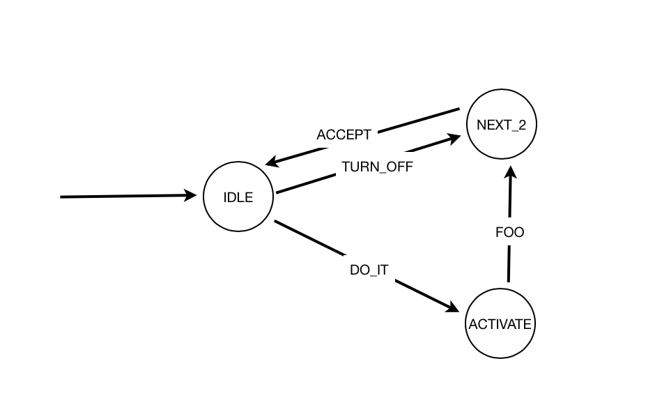
It is usefull to represent a state machine as a graph with states as nodes and actions as arrows:
|
In most cases one of states is distinguished from others: this is an initial state, the first state you start your system. There can be also a set of other special states -- every time you reach one of them, something unusual must have happened. For example STOP state may mean a contoled stop of your system, while TERMINATE may mean an uncontrolled stop of your system being a result of some unexpected data or component malfunction. I classify STOP as an unusual state because typically every system, when started is expected to run forever.
If you hava a definition of a state machine (you know a set of sates, actions and all possible transitions) you can easily "execute" it with te code similar to the follwing:
|
1 2 3 4 5 6 7 8 9 10 11 12 13 14 15 16 17 18 19 20 21 22 23 24 25 26 27 28 29 30 31 |
initialState = START routes = [{...}, ... {...}] currentState = initialState while (currentState != STOP) { action = getAction() if(action != ACTION_NONE){ if (action == TERMINATE) { currentState = TERMINATE break } noRoute = TRUE for route in routes { if (currentState == route["currentState"] AND action == route["action"]) { currentState = route["newState"] executeState(currentState) noRoute = FALSE break } } if (currentState == TERMINATE || noRoute == TRUE) { break } } } |
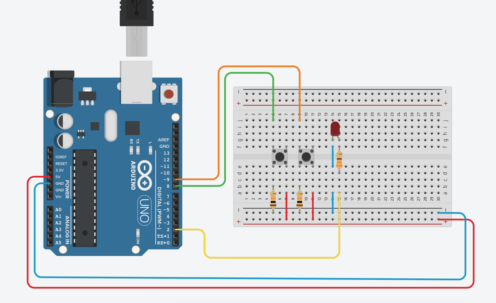
In this example you will work with a very simple circuit:
|
As you can see, there are:
- Arduino Uno board to control all the interactions.
- LED controlled by Arduino Uno in response to button press action.
- Button
ONconnected with green wire to the Arduino. You will use this button to turn LEDON. - Button
OFFconnected with orange wire to the Arduino. You will use this button to turn LEDOFF.
In the "classical" approach probably you will write code more o less similar to the following:
|
1 2 3 4 5 6 7 8 9 10 11 12 13 14 15 16 17 18 19 20 21 22 23 24 25 26 27 28 29 30 31 32 33 34 35 36 37 38 39 40 41 42 43 44 45 46 47 48 49 50 51 52 53 |
#define PIN_LED 2 #define PIN_BTN_ON 8 #define PIN_BTN_OFF 9 #define BTN_INACTIVE 0 #define BTN_ON_PRESS 1 #define BTN_OFF_PRESS 2 int button; void setup() { pinMode(PIN_LED, OUTPUT); pinMode(PIN_BTN_ON, INPUT); pinMode(PIN_BTN_OFF, INPUT); digitalWrite(PIN_LED, LOW); button = BTN_INACTIVE; } int checkButtonState(){ if(digitalRead(PIN_BTN_ON) == HIGH){ delay(20); while(digitalRead(PIN_BTN_ON) == HIGH); delay(20); return BTN_ON_PRESS; } else if(digitalRead(PIN_BTN_OFF) == HIGH){ delay(20); while(digitalRead(PIN_BTN_OFF) == HIGH); delay(20); return BTN_OFF_PRESS; } return BTN_INACTIVE; } void loop() { button = checkButtonState(); if (button == BTN_ON_PRESS){ digitalWrite(PIN_LED, HIGH); } else if (button == BTN_OFF_PRESS){ digitalWrite(PIN_LED, LOW); } } |
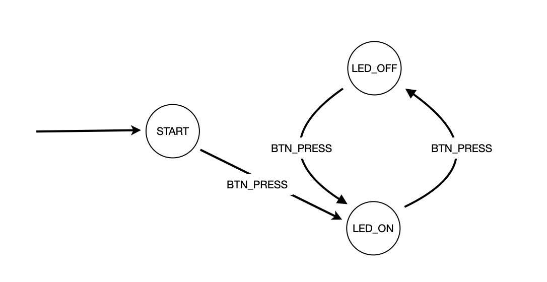
This system can be also control with the following state machine:

|
State machine depicetd on the above image is implemented below:
|
1 2 3 4 5 6 7 8 9 10 11 12 13 14 15 16 17 18 19 20 21 22 23 24 25 26 27 28 29 30 31 32 33 34 35 36 37 38 39 40 41 42 43 44 45 46 47 48 49 50 51 52 53 54 55 56 57 58 59 60 61 62 63 64 65 66 67 68 69 70 71 72 73 74 75 76 77 78 79 80 81 82 83 84 85 86 87 88 89 90 91 92 93 94 95 96 97 98 99 100 101 102 103 104 105 106 107 108 109 110 111 112 113 114 115 116 117 118 119 120 121 122 123 124 125 126 127 128 129 130 131 132 133 134 135 136 137 138 139 140 141 142 143 144 |
#define TRUE 1 #define FALSE 0 #define PIN_LED 2 #define PIN_BTN_ON 8 #define PIN_BTN_OFF 9 #define BTN_INACTIVE 0 #define BTN_ON_PRESS 1 #define BTN_OFF_PRESS 2 #define STATE_TERMINATE (-2) #define STATE_STOP (-1) #define STATE_START 0 #define STATE_STATE_LED_ON 1 #define STATE_STATE_LED_OFF 2 #define INITIAL_STATE STATE_START #define ACTION_TERMINATE (-1) #define ACTION_BTN_ON_PRESS 1 #define ACTION_BTN_OFF_PRESS 2 #define ACTION_NONE 3 #define NUMBER_OF_ROUTES 4 #define INDEX_STATE_CURRENT 0 #define INDEX_ACTION 1 #define INDEX_STATE_NEXT 2 // Warning!!! // Remember to update NUMBER_OF_ROUTES when changing routing table int smRoutes[NUMBER_OF_ROUTES][3] = { {STATE_START, ACTION_BTN_ON_PRESS, STATE_STATE_LED_ON}, {STATE_START, ACTION_BTN_OFF_PRESS, STATE_STATE_LED_OFF}, {STATE_STATE_LED_ON, ACTION_NONE, STATE_START}, {STATE_STATE_LED_OFF, ACTION_NONE, STATE_START} }; int button; void setup() { pinMode(PIN_LED, OUTPUT); pinMode(PIN_BTN_ON, INPUT); pinMode(PIN_BTN_OFF, INPUT); digitalWrite(PIN_LED, LOW); button = BTN_INACTIVE; } int checkButtonState() { if(digitalRead(PIN_BTN_ON) == HIGH){ delay(20); while(digitalRead(PIN_BTN_ON) == HIGH); delay(20); return BTN_ON_PRESS; } else if(digitalRead(PIN_BTN_OFF) == HIGH){ delay(20); while(digitalRead(PIN_BTN_OFF) == HIGH); delay(20); return BTN_OFF_PRESS; } return BTN_INACTIVE; } int getAction() { button = checkButtonState(); if (button == BTN_ON_PRESS){ return ACTION_BTN_ON_PRESS; } else if (button == BTN_OFF_PRESS){ return ACTION_BTN_OFF_PRESS; } return ACTION_NONE; } void smExecuteSTATE_STATE_LED_ON(){ digitalWrite(PIN_LED, HIGH); } void smExecuteSTATE_STATE_LED_OFF(){ digitalWrite(PIN_LED, LOW); } void smExecuteState(int currentState) { switch (currentState){ case STATE_START: { break; } case STATE_STATE_LED_ON: { smExecuteSTATE_STATE_LED_ON(); break; } case STATE_STATE_LED_OFF: { digitalWrite(PIN_LED, LOW); break; } } } void smExecute(int initalState) { int currentState = initalState; int action; int noRoute; int r; while (currentState != STATE_STOP) { action = getAction(); if(action != ACTION_NONE){ if (action == ACTION_TERMINATE) { currentState = STATE_TERMINATE; break; } noRoute = TRUE; for(r=0; r<NUMBER_OF_ROUTES; ++r){ if (currentState == smRoutes[r][INDEX_STATE_CURRENT] && action == smRoutes[r][INDEX_ACTION]) { currentState = smRoutes[r][INDEX_STATE_NEXT]; smExecuteState(currentState); noRoute = FALSE; break; } } } if (currentState == STATE_TERMINATE || noRoute == TRUE) { break; } } } void loop() { smExecute(INITIAL_STATE); } |
At this moment this may seem like an unnecessary complication of simple things, but I hope you will appreciate this approach in subsequent, more and more complex versions of this system.
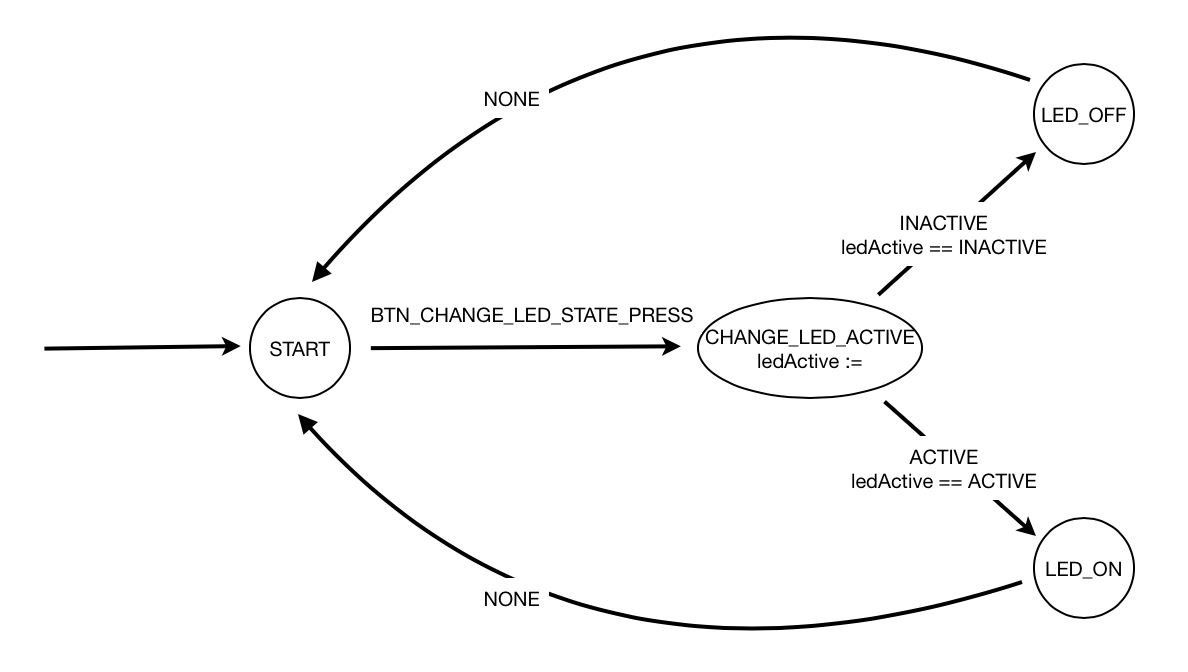
In this example you will use sligtly modfied version of circuit from example 1: there is only one button to turn led on or off.
Susprisingly, one button simplifies the design a lot:
|
|
1 |
However I propose you to work with the state machine given below. There are two reasons for that:
- You will see how to pass control from one state to another with variables.
- It would be easier to extend this state machine in next modiffication of my example.
|
|
1 |
In this example you will use sligtly modfied version of circuit from example 2: you add one more led and second button to select the number of active LEDs -- one or two.

|
|
1 |
In this example you will use exactly the same circuit as in example 3 but will chane LEDs behaviour from constant ligt to blinking.

|
|
1 |