
Published: 2023-12-31
Last update: 2024-01-01
In this tutorial you will learn about another one solution you can apply in case of lack of pins. You will learn how to use shift register to control multiple outputs. Doing this you will also learn what a 7-segments LEDs display is.
Table of contents:
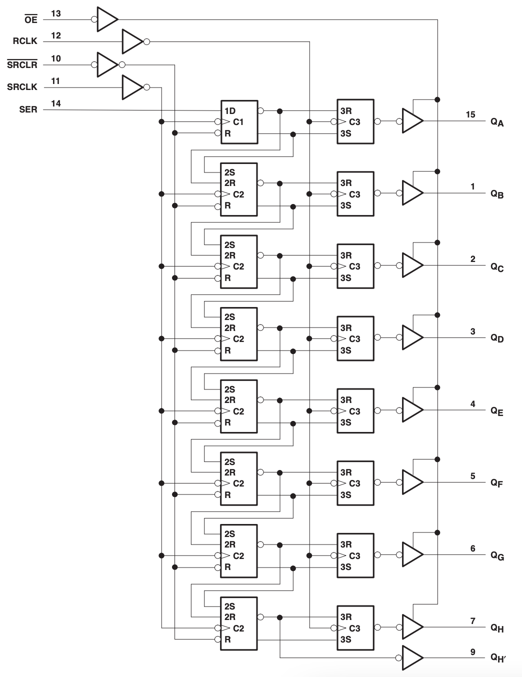
To better understand how shift register works you may take a closer look to it's internal structure (see SN74HC595.pdf
|
At first sight it looks to be a quite complicated but it is not so difficult to understand as it has a repetitive nature. There are:
- four control pins:
- one input pin:
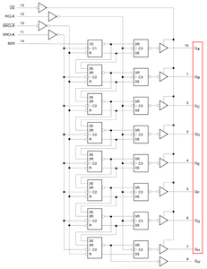
- eight output pins:
- one output pin used to chain multiple shift registers into one biger shift register:

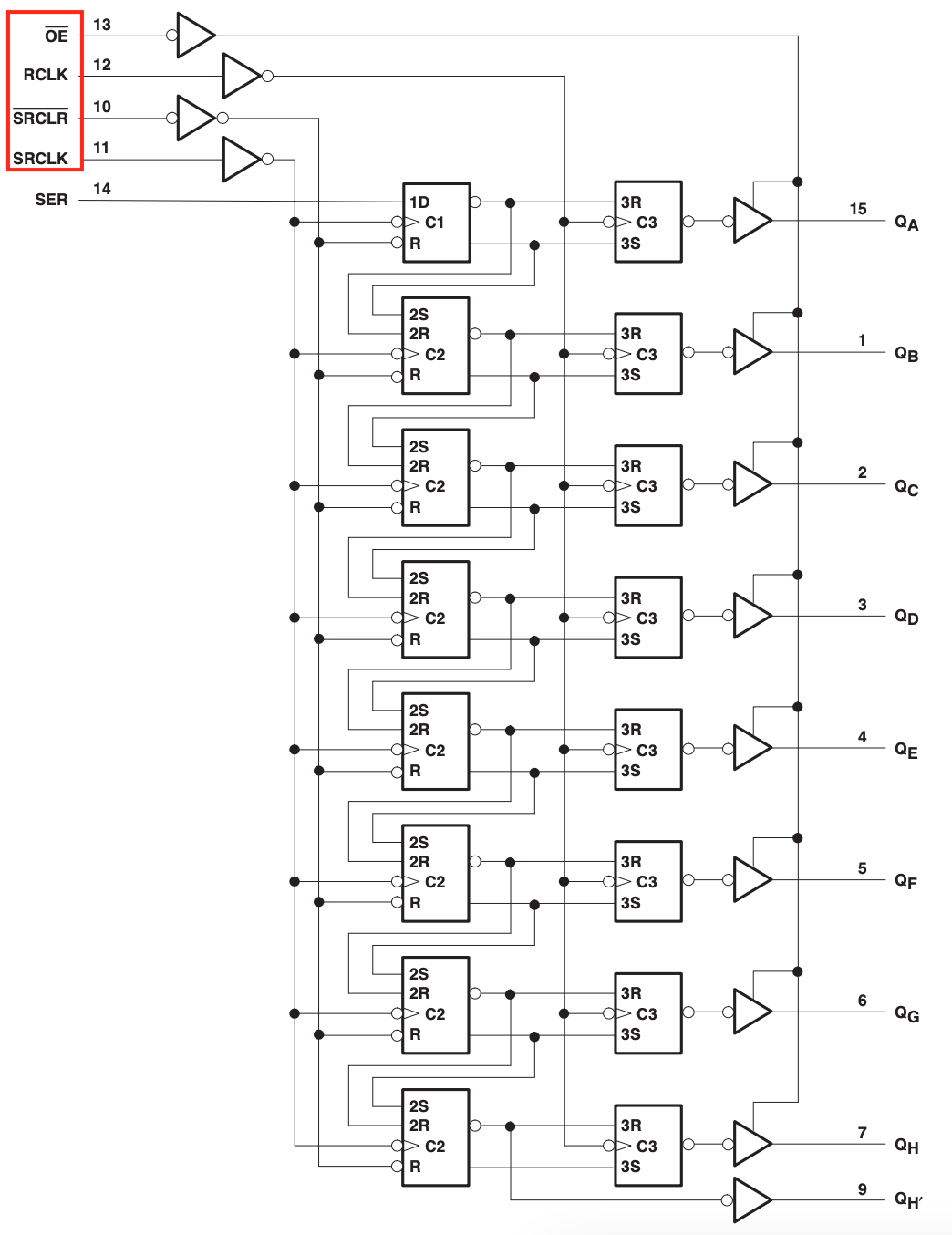


Internally it consist of 16 flip-flops (see 555 topic where I briefly describe flip-flop) divided into two groups, name them "green" group and "orange" group:

|
Each flip-flop store one bit of data. Registers from green group are named shift registers, while registers from orange group are named storage registers or latch registers. You can think about the green group of registers as a working memory which state is not directly visible to the user. When you finish setting the green group than you copy data from the green group to the orange group and, if only OE pin is active, you will see changes in outputs.
Notice that OE pin, as well as SRCLR pin, have a line over it name, which means it operate in "negative logic". Negative logic reverse generally accepted meaning of HIGH state as accepting or enabling and LOW state as rejecting or disabling. So when you see line over pin's name it means that for this pin LOW state is enabling state, while HIGH state is a disabling state.
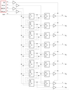
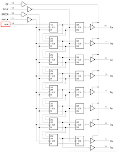
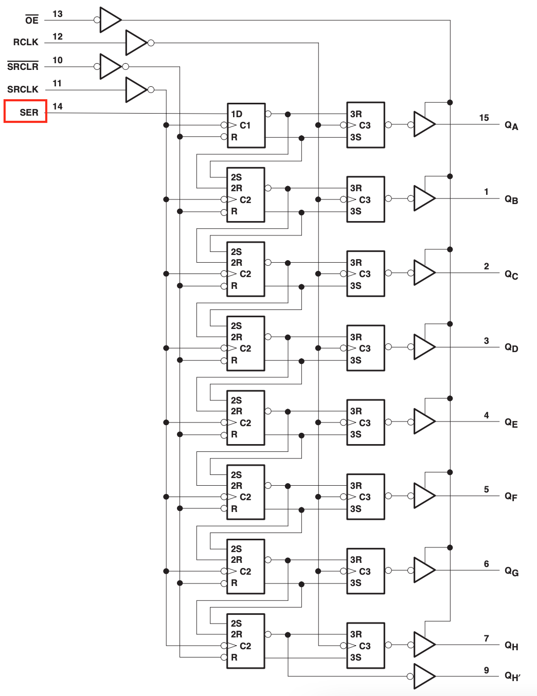
Because shift register has only one input pin, so you have to push data one by one, bit by bit. Every time you provide a bit to
SER (Serial Input) pin it is stored in one register. Which one? I will explain this in steps.
- Set
SERpin to required state, eitherHIGHorLOWcorresponding to bits 1 or 0 respectively. - Inform module, that
SERis ready to be stored. You do this providingHIGHstate toSRCLK(Shift Register Clock) pin. - State from
SERpin is "saved" in the top most flip-flop from green group. - Inform module, that you are going to set new value on pin
SERand setSRCLKpin toLOWstate. You have to do this even if your new value is not really new and is the same as previous, for example when you want to save 1 coming after 1. - Set
SERpin to required state. - Inform module, that
SERis ready to be stored. You do this providingHIGHstate toSRCLK(Shift Register Clock) pin. - State from
SERpin is "saved" in the top most flip-flop from green group. Before this, its previous value is "copied" to the second top most flip-flop from green group. - Set
SRCLKpin toLOWstate. - Set
SERpin to required state. - Inform module, that
SERis ready to be stored. You do this providingHIGHstate toSRCLK(Shift Register Clock) pin. - State from
SERpin is "saved" in the top most flip-flop from green group. Before this, value from second top most flip-flop is "copied" to the third top most flip-flop and value from first top most flip-flop is "copied" to the second top most flip-flop. - Set
SRCLKpin toLOWstate. - Continue last four steps until you provide eight bits of data. Of course providing eight bits is not mandatory – you may stop this procedure on the first bit. You may ask: What if I provide another one, ninth bit? Almost nothing unexpected: again all bits will be shifted and you will lost the first provided bit. You may save them if you join multiple modules -- see part Join two shift registers to light more LEDs in a line.
Being more precise, this copy behavior is executed every time for all flip-flops at once, regardless it is the first, fifth or eighth bit. Whenever you apply a clock pulse to a module (changing SRCLK signal from LOW to HIGH), all bits stored in the green group of flip-flops move one step: flip-flop 7 accepts the value that was previously in flip-flop 6, flip-flop 6 gets the value of flip-flop 5 etc. Finally, flip-flop 0 accepts the current value on data pin SER.
At this moment the green group of flip-flops is completely set-up and they are ready to be copied to storage registers (orange group of flip-flops). You copy form the first grup to the second providing HIGH to RCLK and switch again to LOW just after this. Now all data are copied so you can do what you want with working registers – this will not affect storage registers as long as you will keep RCLK in LOW state.
One last thing left to be done: move bits to the outputs enabling them to the user. You do this activating OE pin as it was stated before.
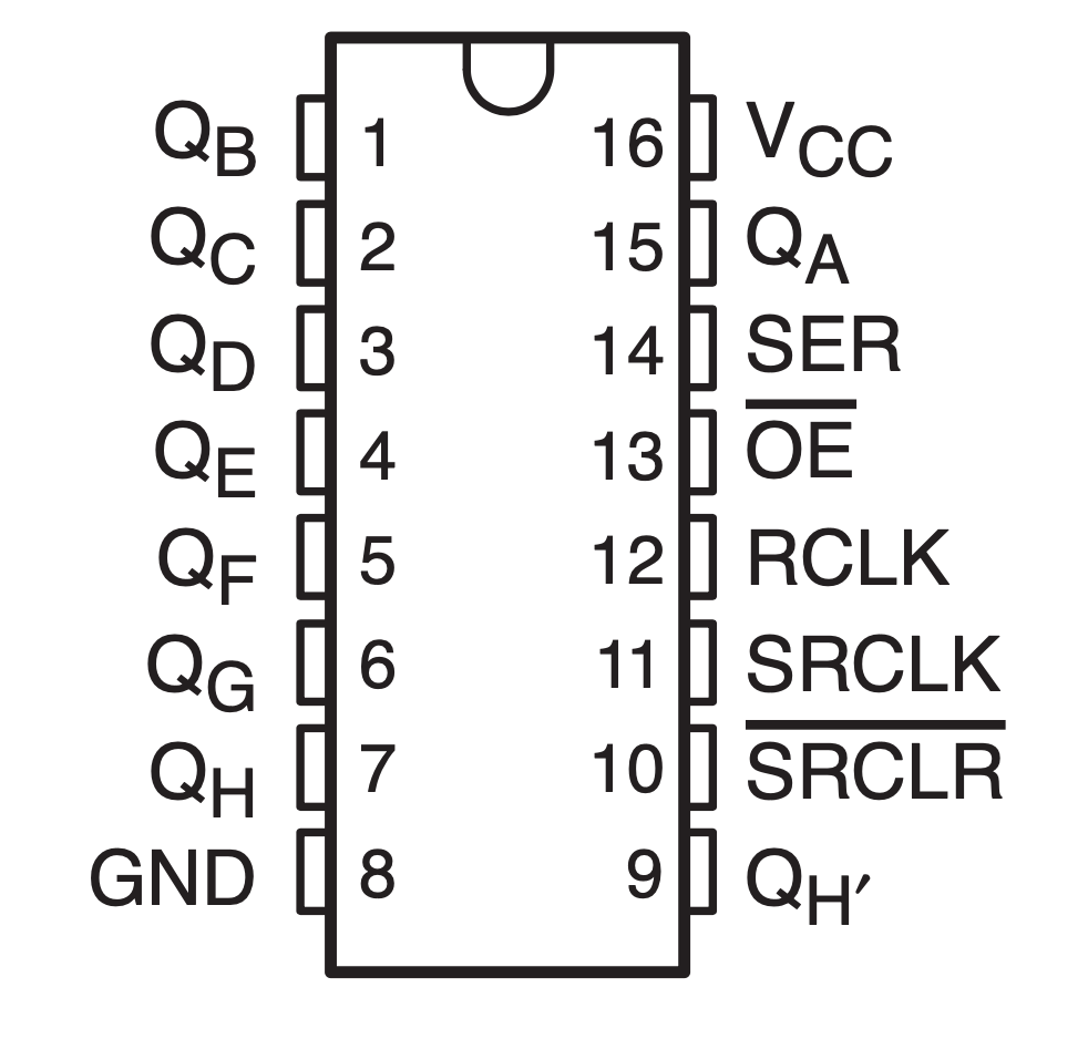
In this part you will use shift register in a typical DIP-16 package:

|
Now, as you have a good understanding of the role of all sections and pins of shift register, I can make a short summary:
|
SER(Serial Input, pin number14) is used to feed data into the module one bit at a time.SRCLK(Shift Register Clock,11) activate move of bits: 6 to 7, 5 to 6 etc. and finally bit from input to 0.RCLK(Register Clock,12) when drivenHIGH, the contents of shift registers are copied into the storage registers.SRCLR(Shift Register Clear,10) allows to reset the entire shift register, making all bits 0, at once. This pin is negative logic.OE(Output Enable,13) enable bits from storage registers to be visible on outputs. This pin is negative logic.QA-QH-- outputs,15and1-7.QH'-- output which you will use in case of chaining multiple modules,9.
shiftOut functionTo control shift register module you have to do few actions, as I explained above. They are quite simple but it is important to have all of them properly synchronized. To save your time, Arduino provides a ready to use function
shiftOut dedicated to push 8 bits into shift register.
Arduino's shiftOut function is very simple and easy to understand. It shifts out a byte of data one bit at a time. Starts from either the most (i.e. the leftmost) or least (rightmost) significant bit. Each bit is written in turn to a data pin, after which a clock pin is pulsed (taken HIGH, then LOW) to indicate that all bits in shift registers should be shifted to make a free place for a new bit.
You can find it's code in the wiring_shift.c file:
|
1 2 3 4 5 6 7 8 9 10 11 12 13 14 |
void shiftOut(uint8_t dataPin, uint8_t clockPin, uint8_t bitOrder, uint8_t val) { uint8_t i; for (i = 0; i < 8; i++) { if (bitOrder == LSBFIRST) digitalWrite(dataPin, !!(val & (1 << i))); else digitalWrite(dataPin, !!(val & (1 << (7 - i)))); digitalWrite(clockPin, HIGH); digitalWrite(clockPin, LOW); } } |
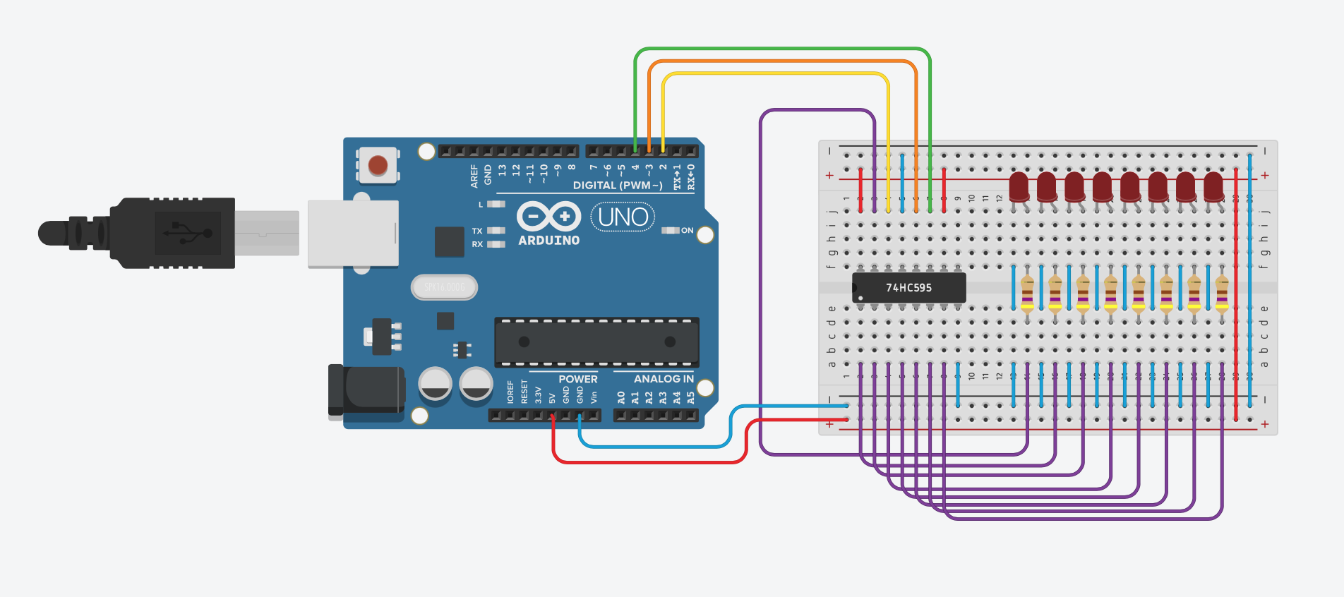
To make a tests in this section you will start with the following circuit:
|
- Pin connected permanently
16,VCC, red wire, connected with+5;13,!OE, blue wire, connected permanently withGNDso any changes in the output section of flip-flops (orange section) is immediately visible to the user;10,!SRCLR, red wire, connected permanently with+5; when negative clears all flip-flops;8,GND, blue wire, connected permanently withGND;
- Control pins
14,SER, yellow wire, connected with microcontroller's pin number2; here you provide your data;12,RCLK, orange wire, connected with microcontroller's pin number3; copy data from green section of flip-flops to the orange section of flip-flops;11,SRCLK, green wire, connected with microcontroller's pin number4; when activated shifts all data by one and saves bit provided onSERpin;
- Outpu pins
15,Q_A, output from the first (1) flip-flop;1,Q_B, output from the first (2) flip-flop;2,Q_C, output from the first (3) flip-flop;3,Q_D, output from the first (4) flip-flop;4,Q_E, output from the first (5) flip-flop;5,Q_F, output from the first (6) flip-flop;6,Q_G, output from the first (7) flip-flop;7,Q_H, output from the first (8) flip-flop;
- Unused pins
9,Q_H_PRIME, not connected, negated output from the eight (8) flip-flop;
|
1 2 3 4 5 6 7 8 9 10 11 12 13 14 15 16 17 18 19 20 21 22 23 24 25 26 27 28 29 30 31 32 33 34 |
#define PIN_SER 2 #define PIN_SRCLK 4 #define PIN_RCLK 3 // 1 // 2 6 3 1 // 8 4 2 6 8 4 2 1 // // 1 1 1 1 1 1 1 1 = 255 // 0 0 0 0 0 0 0 0 = 0 uint8_t val = 0; void shiftRegisterCopy(uint8_t storageRegisterClockPin) { digitalWrite(storageRegisterClockPin, HIGH); digitalWrite(storageRegisterClockPin, LOW); } void setup() { pinMode(PIN_SER, OUTPUT); pinMode(PIN_RCLK, OUTPUT); pinMode(PIN_SRCLK, OUTPUT); digitalWrite(PIN_SER, LOW); digitalWrite(PIN_RCLK, LOW); digitalWrite(PIN_SRCLK, LOW); } void loop() { shiftOut(PIN_SER, PIN_SRCLK, LSBFIRST, val); shiftRegisterCopy(PIN_RCLK); delay(1000); val = val == 255 ? 0 : 255; } |
|
1 2 3 4 5 6 7 8 9 10 11 12 13 14 15 16 17 18 19 20 21 22 23 24 25 26 27 28 29 30 31 32 33 34 35 36 37 38 39 40 41 42 43 |
#define PIN_SER 2 #define PIN_SRCLK 4 #define PIN_RCLK 3 // 1 // 2 6 3 1 // 8 4 2 6 8 4 2 1 // // 1 0 0 0 0 0 0 0 = 128 // 0 1 0 0 0 0 0 0 = 64 // 0 0 1 0 0 0 0 0 = 32 // 0 0 0 1 0 0 0 0 = 16 // 0 0 0 0 1 0 0 0 = 8 // 0 0 0 0 0 1 0 0 = 4 // 0 0 0 0 0 0 1 0 = 2 // 0 0 0 0 0 0 0 1 = 1 uint8_t val = 128; void shiftRegisterCopy(uint8_t storageRegisterClockPin) { digitalWrite(storageRegisterClockPin, HIGH); digitalWrite(storageRegisterClockPin, LOW); } void setup() { pinMode(PIN_SER, OUTPUT); pinMode(PIN_RCLK, OUTPUT); pinMode(PIN_SRCLK, OUTPUT); digitalWrite(PIN_SER, LOW); digitalWrite(PIN_RCLK, LOW); digitalWrite(PIN_SRCLK, LOW); } void loop() { shiftOut(PIN_SER, PIN_SRCLK, LSBFIRST, val); shiftRegisterCopy(PIN_RCLK); delay(1000); val = val >> 1; if (val == 0) { val = 128; } } |
For this test you have to modify your circuit doubling breadboard with all the components:
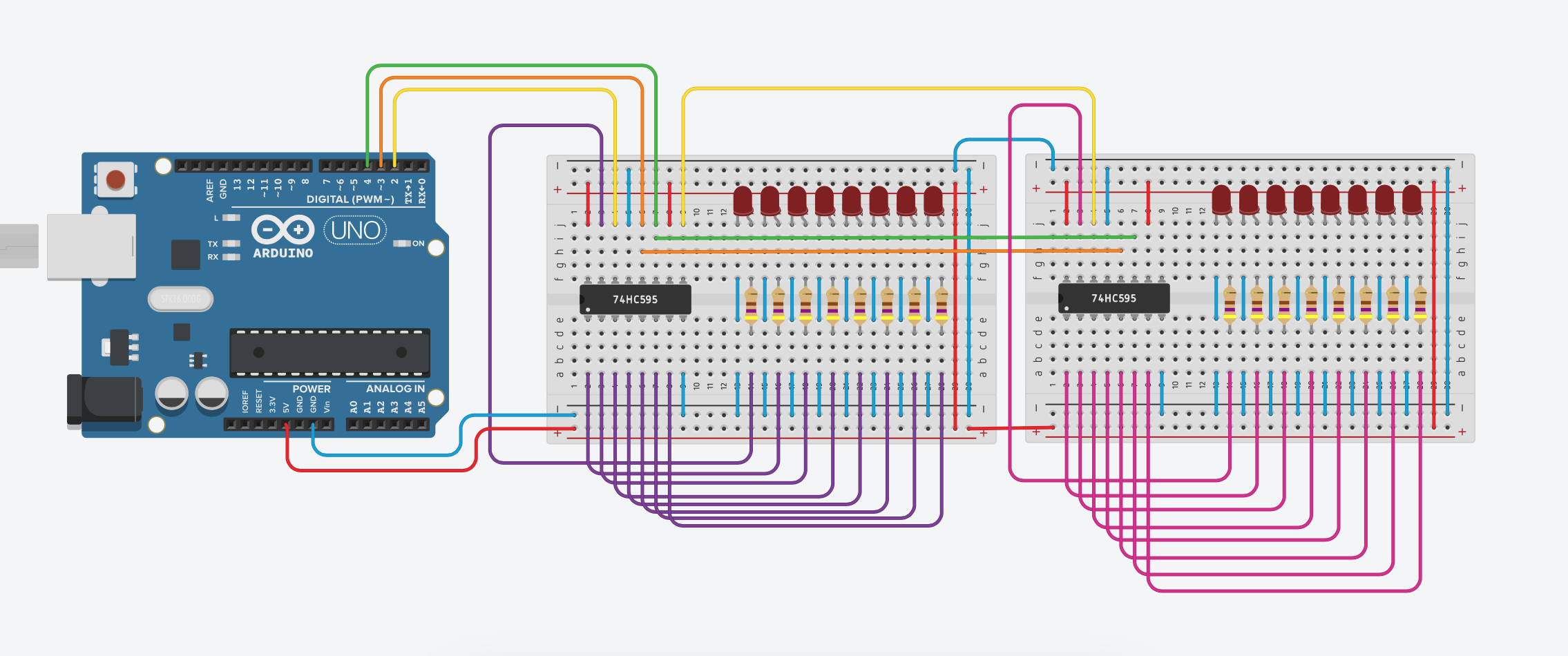
|
Because now you have two shift registers, each time you have to push two bytes – first is the least significant byte than the most significant:
|
1 2 3 4 5 6 7 8 9 10 11 12 13 14 15 16 17 18 19 20 21 22 23 24 25 26 27 28 29 30 31 32 33 34 35 36 37 38 39 40 41 42 43 44 45 46 47 48 49 50 51 52 53 54 55 56 57 58 |
#define PIN_SER 2 #define PIN_SRCLK 4 #define PIN_RCLK 3 // 1 // 2 6 3 1 // 8 4 2 6 8 4 2 1 // // 1 0 0 0 0 0 0 0 = 128 // 0 1 0 0 0 0 0 0 = 64 // 0 0 1 0 0 0 0 0 = 32 // 0 0 0 1 0 0 0 0 = 16 // 0 0 0 0 1 0 0 0 = 8 // 0 0 0 0 0 1 0 0 = 4 // 0 0 0 0 0 0 1 0 = 2 // 0 0 0 0 0 0 0 1 = 1 int i; uint8_t val[16][2] = {{ 0,128}, { 0, 64}, { 0, 32}, { 0, 16}, { 0, 8}, { 0, 4}, { 0, 2}, { 0, 1}, {128, 0}, { 64, 0}, { 32, 0}, { 16, 0}, { 8, 0}, { 4, 0}, { 2, 0}, { 1, 0}}; void shiftRegisterCopy(uint8_t storageRegisterClockPin) { digitalWrite(storageRegisterClockPin, HIGH); digitalWrite(storageRegisterClockPin, LOW); } void setup() { pinMode(PIN_SER, OUTPUT); pinMode(PIN_RCLK, OUTPUT); pinMode(PIN_SRCLK, OUTPUT); digitalWrite(PIN_SER, LOW); digitalWrite(PIN_RCLK, LOW); digitalWrite(PIN_SRCLK, LOW); } void loop() { for (i=0; i<16; i++) { shiftOut(PIN_SER, PIN_SRCLK, LSBFIRST, val[i][0]); shiftOut(PIN_SER, PIN_SRCLK, LSBFIRST, val[i][1]); shiftRegisterCopy(PIN_RCLK); delay(100); } } |
Above code is correct for any combination of two bytes. For this task you can implement it differently to shift each time only one bit instead of 16 bits. Approach is quite simple. First you out one bit 1 and next you shift it providing 15 times to the input bit 0:
|
1 2 3 4 5 6 7 8 9 10 11 12 13 14 15 16 17 18 19 20 21 22 23 24 25 26 27 28 29 30 31 32 33 34 35 36 37 |
#define PIN_SER 2 #define PIN_SRCLK 4 #define PIN_RCLK 3 int i; void shiftRegisterCopy(uint8_t storageRegisterClockPin) { digitalWrite(storageRegisterClockPin, HIGH); digitalWrite(storageRegisterClockPin, LOW); } void setup() { pinMode(PIN_SER, OUTPUT); pinMode(PIN_RCLK, OUTPUT); pinMode(PIN_SRCLK, OUTPUT); digitalWrite(PIN_SER, LOW); digitalWrite(PIN_RCLK, LOW); digitalWrite(PIN_SRCLK, LOW); } void loop() { digitalWrite(PIN_SER, 1); digitalWrite(PIN_SRCLK, HIGH); digitalWrite(PIN_SRCLK, LOW); shiftRegisterCopy(PIN_RCLK); delay(1000); for (i=2; i<=16; i++) { digitalWrite(PIN_SER, 0); digitalWrite(PIN_SRCLK, HIGH); digitalWrite(PIN_SRCLK, LOW); shiftRegisterCopy(PIN_RCLK); delay(1000); } } |
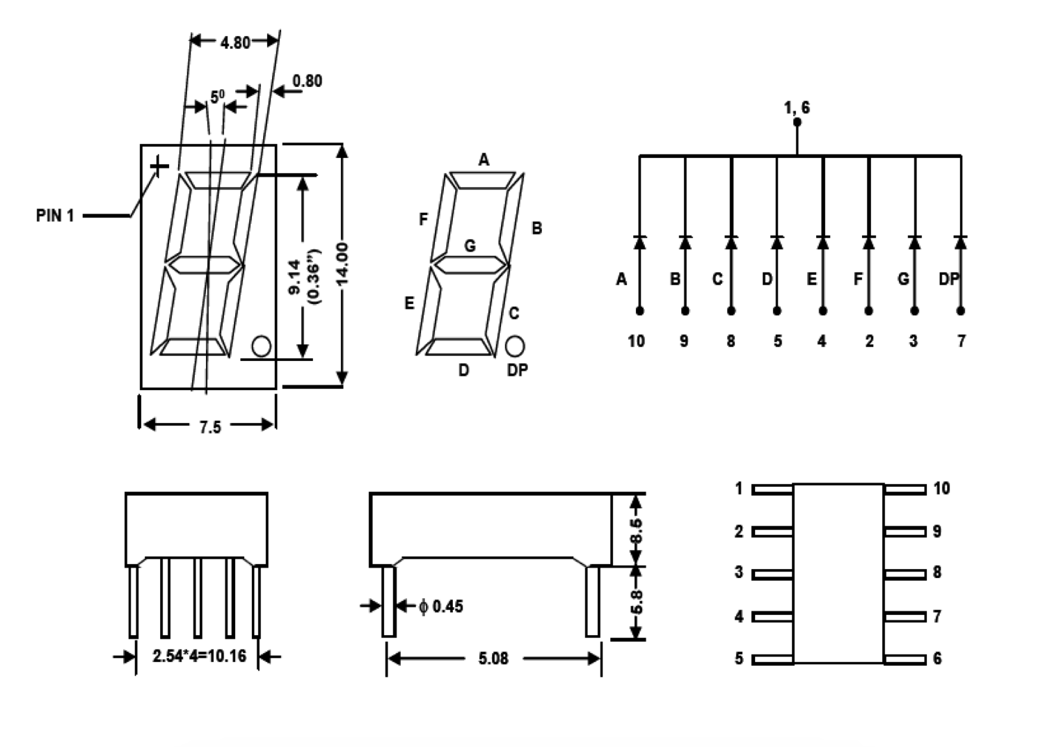
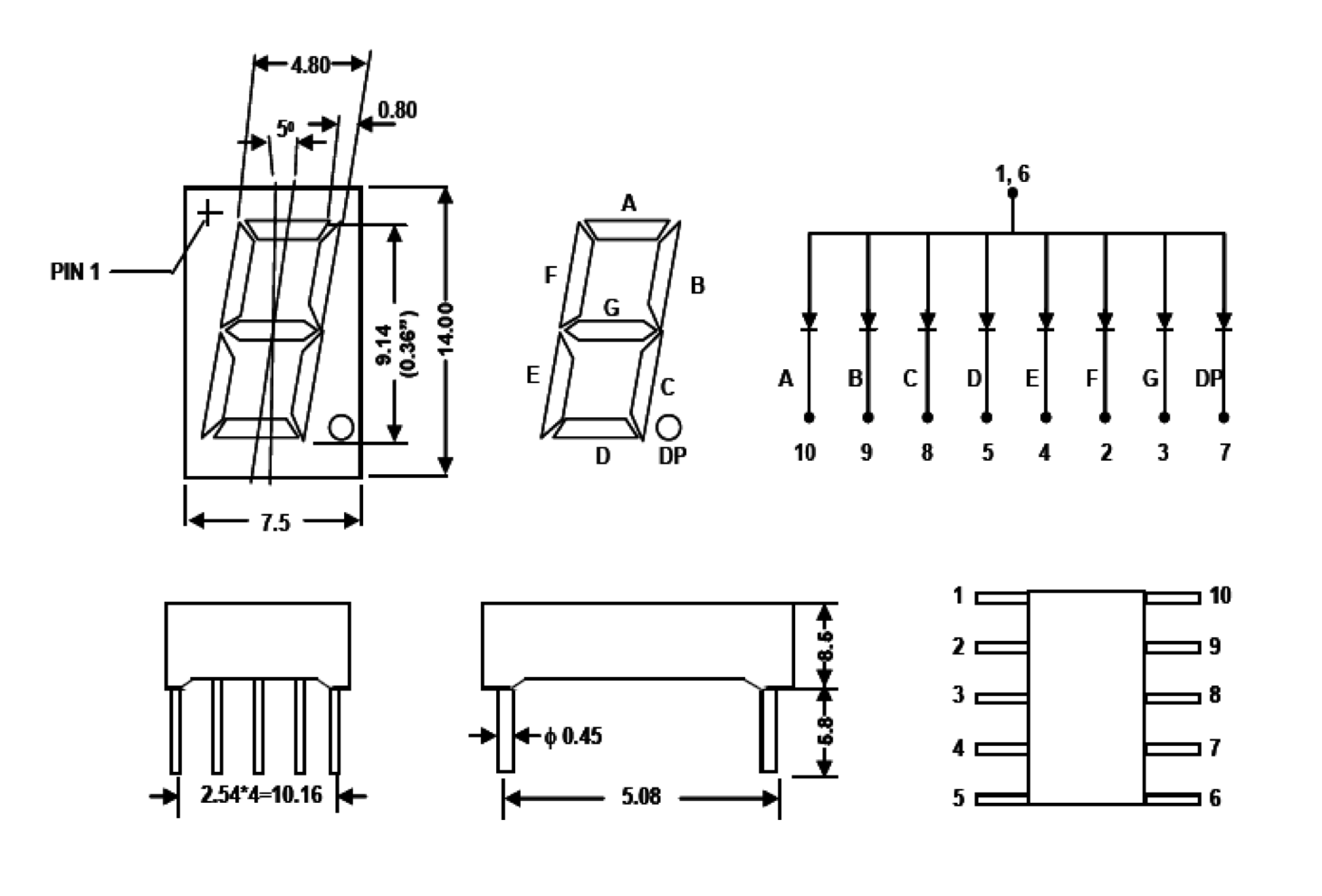
Seven-segment displays may use a different technology for displaying but now you will focus on those based on a light-emitting diodes (LEDs). A seven-segment display is a form of electronic display device for displaying decimal numerals (and in a limited way some letters) that is an alternative to the more complex dot matrix displays.
This display has nothing more than 7 LEDs inside it. These LEDs are separated into each segments typically named as A, B, C, D, E, F, G (and sometimes DP to control decimal point) as shown in the picture below:

|
| 7-segments LEDs display and its segments |
In a simple one digit LED package, typically all of the cathodes (negative terminals) or all of the anodes (positive terminals) of the segment LEDs are connected and brought out to a common pin; this is referred to as a "common cathode" or "common anode" device (documentation: source, local copy of: Soldered_LD3361BS_datasheet.pdf ![]() ):
):
|
|
| Left: Common cathode (common negative) Right: Common anode (common positive) | |
So to make an LED of a particular segment glow you just have to power common pin along with the selected segment pin. This way you can power more than one segment at a time.
| Digit | Display | Segments | Hexadecimal code | |||||||
|---|---|---|---|---|---|---|---|---|---|---|
| A | B | C | D | E | F | G | ABCDEFG | GFEDCBA | ||
| 0 |  |
1 | 1 | 1 | 1 | 1 | 1 | 0 | 0x7E | 0x3F |
| 1 |  |
0 | 1 | 1 | 0 | 0 | 0 | 0 | 0x30 | 0x06 |
| 2 |  |
1 | 1 | 0 | 1 | 1 | 0 | 1 | 0x6D | 0x5B |
| 3 |  |
1 | 1 | 1 | 1 | 0 | 0 | 1 | 0x79 | 0x4F |
| 4 |  |
0 | 1 | 1 | 0 | 0 | 1 | 1 | 0x33 | 0x66 |
| 5 |  |
1 | 0 | 1 | 1 | 0 | 1 | 1 | 0x5B | 0x6D |
| 6 |  |
1 | 0 | 1 | 1 | 1 | 1 | 1 | 0x5F | 0x7D |
| 7 |  |
1 | 1 | 1 | 0 | 0 | 0 | 0 | 0x70 | 0x07 |
| 8 |  |
1 | 1 | 1 | 1 | 1 | 1 | 1 | 0x7F | 0x7F |
| 9 |  |
1 | 1 | 1 | 1 | 0 | 1 | 1 | 0x7B | 0x6F |
Keep in mind that above codes are correct for common cathode 7-segment LED display. If you have a common anode 7-segment LED display you have to negate all bits because in such case segment is ON when you provide LOW state to its pin.
To make a test in this section please make the following circuit:
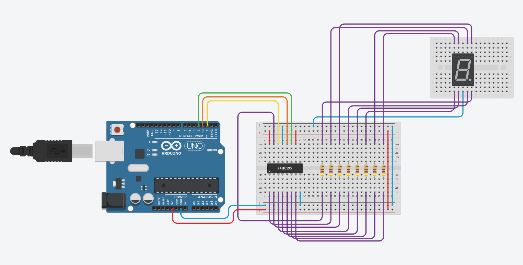
|
|
1 2 3 4 5 6 7 8 9 10 11 12 13 14 15 16 17 18 19 20 21 22 23 24 25 26 27 28 29 30 31 32 33 34 35 36 37 38 39 40 41 |
#define PIN_SER 2 #define PIN_SRCLK 4 #define PIN_RCLK 3 int i; byte digit[] = { 0b01111110, // 7E 0b00110000, // 30 0b01101101, // 6D 0b01111001, // 79 0b00110011, // 33 0b01011011, // 5B 0b01011111, // 5F 0b01110000, // 70 0b01111111, // 7F 0b01111011 // 7B }; void shiftRegisterCopy(uint8_t storageRegisterClockPin) { digitalWrite(storageRegisterClockPin, HIGH); digitalWrite(storageRegisterClockPin, LOW); } void setup() { pinMode(PIN_SER, OUTPUT); pinMode(PIN_RCLK, OUTPUT); pinMode(PIN_SRCLK, OUTPUT); digitalWrite(PIN_SER, LOW); digitalWrite(PIN_RCLK, LOW); digitalWrite(PIN_SRCLK, LOW); } void loop() { for (i=0; i<10; i++) { shiftOut(PIN_SER, PIN_SRCLK, LSBFIRST, digit[i]); shiftRegisterCopy(PIN_RCLK); delay(500); } } |
Please note that in above circuit you use a 7-segments display with a common cathode. If you have a 7-segments display with a common anode, you have to change your circuit a little bit (providing positive power to the common pin instead negative):

|
Because now "active" signal is negative you have to either revert all the bits in digit array or use bitwise NOT operation when you provide last argument in shiftOut function:
|
1 2 3 |
[...] shiftOut(PIN_SER, PIN_SRCLK, LSBFIRST, ~digit[i]); [...] |
There exist also an integrated displays of this type enclosing in one package multiple 7-segment blocks. Some of these integrated displays incorporate their own internal decoder or alternatively allow to operate with each digit independently (documentation: source, local copy of: Soldered_LD3361BS_datasheet.pdf):

However in most cases you should use a some kind of multiplexing (documentation: source, local copy of: Soldered_LD3361BS_datasheet.pdf):
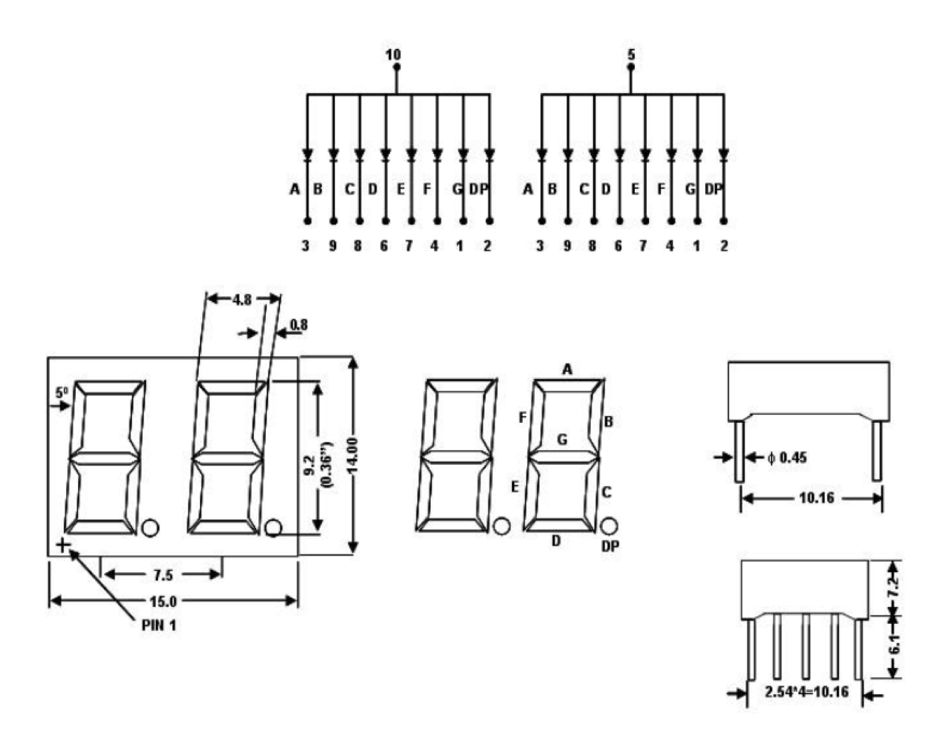
Now I will try to explain how you can control two 7-segment digits with only 10 pins.
Assume that you have a multiple-digit LED displays with common cathodes (common negatives). If you have two digits than you will have two common cathodes: one for first digit and second for second digit. Pins to control segment are the same for the same segments: there is only one pin for segment A which is connected both to segment A of digit one and at the same time to segment A of digit two. The same is with all other segments.
To operate any particular segment of any digit, your controlling circuit would turn on the cathode for the selected digit (say digit one), and the anode pins for the desired segments. This way you will set segments of the first digit. Then after a short delay you turn off the cathode of the selected digit (say digit one), and "activate" the cathode for the next digit (say digit two). Now changing state of the pins controlling anodes you can turn on or off desired segments. Using this kind of multiplexing you can control n digits with only 7 pins (8 if you use decimal point) plus n other pins to select digit.
Although to a naked eye all digits of an LED display appear lit, only one digit is lit at any given time in a multiplexed display. The digit changes at a high enough rate that the human eye cannot see the flashing (although this flickering may be visible when you use a camera).