
In this tutorial you will learn how to transform voltage level to level required by device you want to use.
Table of contents
- Fixed linear voltage regulator
- Examples of fixed linear voltage regulator
- Basic circuit
- Other applications
- Use cases
- Switching converter
- Voltage divider
Let's start from... No, not from the beginning. We have to start from quit complicated electronic circuit (if you would build it from scratch). We will not dive into details of it, but we need it for our further experiments. Why? The answer is simple: for simplicity and our convenience. During our tutorials we will build many circuits and we can power them with different batteries: 4.5V, 5V, 6V, 9V, 12V etc. Imagine that on my tutorials I use 12V powers source but you have only one 9V battery. This could be a problem, because all components' values like resistance, capacity etc would be for you useless force you to recalculate all of them.
On the other side, most of microcontrollers components are powered with 3.3V or 5V. That is why I made a decision to start from circuit which as input takes almost any power source but as output generates every time 3.3V (or 5V). This type of circuits is called voltage regulator. So if you have 3.3V or 5V power adapter you can use it, if not - you have to build this circuit and use it in all of our experiments.
At this point we can say
A voltage regulator is designed to automatically maintain a constant voltage level.
We will use one of many different types: a fixed linear voltage regulator.
Using linear voltage regulator you have to take into account that all of them require an input voltage at least some minimum amount higher than the desired output voltage. That minimum amount is called the dropout voltage. For example, a common regulator such as the 7805 has an output voltage of 5V, but can only maintain this if the input voltage remains above about 7V. Its dropout voltage is therefore 7V − 5V = 2V. When the supply voltage is less than about 2V above the desired output voltage, so-called low dropout regulators (LDOs) must be used.
As a rule of thumb we have to remember that for linear voltage regulator the input voltage must always be higher than the output voltage by some minimum amount. This ,,amount'' depends on type of regulator: if is it LOD or not. Please try to find information about dropout voltage in datasheet of some regulators (see further). For example in LDO 3,3V LF33CV datasheet we can find 0.7V while in 5V L7805CV we have 2.5V.
Because LODs seems to be better than non LODs regulators we can ask why we care about non LODs regulators. The answer is simple: because of money - see table below.
| Type | Max. current [A] | Dropout voltage [V] | Price [PLN] |
|---|---|---|---|
| LDO 3,3V LM1117T | 0.8 | 1.2 | 3.90 |
| LDO 3,3V LD1117T | 0.8 | 1.2 | 2.50 |
| LDO 3,3V LF33CV | 0.5 | 0.7 | 2.90 |
| 5V L7805CV | 1.5 | 2.5 | 0.90 |
| 5V L7805AVB | 1 | 2.5 | 0.80 |
| LDO 5V LM1117T | 0.8 | 1.4 | 4.50 |
Sometimes prices will be given in PLN which is the currency of Poland where I live. The currency we use doesn't matter - the ratio of two product is important. For example from the above table we can see that LDO 5V LM1117T which costs 4.50PLN is 5.625 times more expensive compared to 5V L7805AVB which costs 0.80PLN. The ratio stays, more or less, constant for different currencies.
In this type regulator design, the input current required is always the same as the output current. As the input voltage must always be higher than the output voltage, this means that the total power (voltage multiplied by current - see formula below) going into regulator will be more than the output power provided. The difference is dissipated as heat. This means both that for some applications an adequate heatsink must be provided, and also that a (often substantial) portion of the input power is wasted during the process, rendering them less efficient than some other types of power supplies. We may prefer buck converters (see further) over linear regulators because they are more efficient and do not require heat sinks, but they are more expensive.
An equation to calculate the powe we waste as a heat is as follow
$$P=(V_{in}-V_{out})I$$
where
- $V_{in}$ - input voltage,
- $V_{out}$ - output voltage,
- $I$ - current.
Simple linear regulators may only contain a Zener diode and a series resistor; more complicated regulators include separate stages of voltage reference, error amplifier and power pass element. Because a linear voltage regulator is a common element of many devices, integrated circuit regulators, as discussed above, are very common.
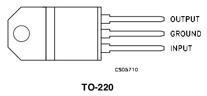
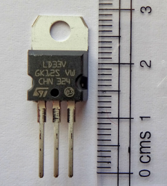
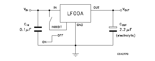
Let's take a closer look at some exemplary fixed linear voltage regulator
LFxx datasheet

LD1117 datasheet
(they are pretty much the same, just versions from different manufacturers: LM - National Semiconductor, LD - SGS-Thomson Eicroelectronics)

LD1117 datasheet
(they are pretty much the same, just versions from different manufacturers: LM - National Semiconductor, LD - SGS-Thomson Eicroelectronics)


Lx780x datasheet
Please pay an attention to pinouts (connections) and check it twice before use if you don't want to damage your regulator. Compare for example pinouts for LDO 3.3V LF33CV and LDO 5V LD1117T.
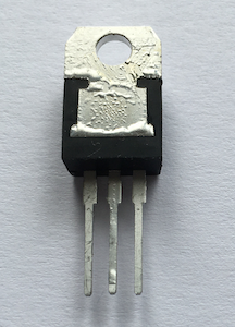
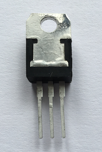
Below you can find two examples of damaged regulators being results of incorrect wiring:
|
|
From LF33CV documentation:
From LD1117T documentation:

Close to real view of components location for LD1117T documentation:
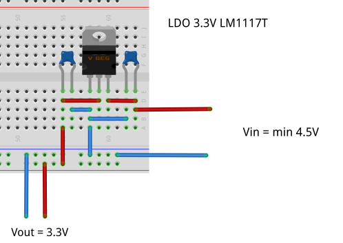
Again (almost) the same circuit but step by step:

|

|

|

|

|

|

|

|

|

|

|

|

|
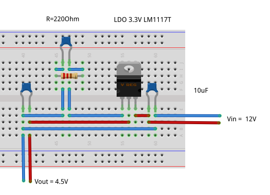
| 1 Ohm | 3.35V |
| 27 Ohm | 3.48V |
| 180 Ohm | 4.3V |
| 220 Ohm | 4.5V |
| 330 Ohm | 5V |
| 560 Ohm | 6.4V |
| 750 Ohm | 7.3V |
| 1k Ohm | 8.1V |
| 10k Ohm | 11.6V |


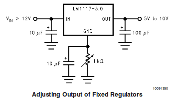
|

|

|
When the output regulated voltage must be higher than the available input voltage, no linear regulator will work. In this situation, something like a switched-mode power supply. Switching converters provide much greater power efficiency as DC-to-DC converters than linear regulators, which are simpler circuits and waste some amount of power as heat.
We have two main types of switching converters
- A boost converter (step-up converter) is a DC-to-DC power converter that steps up voltage (while stepping down current) from its input (supply) to its output (load).
- A buck converter (step-down converter) is a DC-to-DC power converter which steps down voltage (while stepping up current) from its input (supply) to its output (load).

|

|
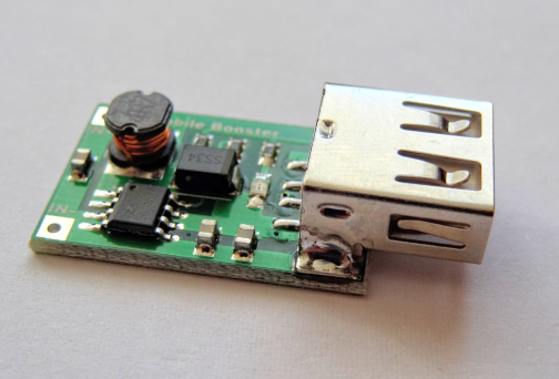
|

|

|

|
| Left image: HW-045 step-up switching converter. Right image: HW-411 step-down switching converter. | |
The most basic converters of this type costs about 10-15PLN which is 3-5 times more expensive than linear regulator.
We will not discuss this topic here. Todo (id=power:step-up converter): Describe switching (step-up/step-down) converter
Maybe you heard about voltage divider and, partly rightly, you conclude that such circuit reduce (divide) input voltage into required output voltage. Your reasoning can be strengthened by the fact that on the Internet you will find many examples showing the use of a voltage divider (in the form of potentiometer) to, for example, provide variable voltage influencing the rotational speed of a DC motor:
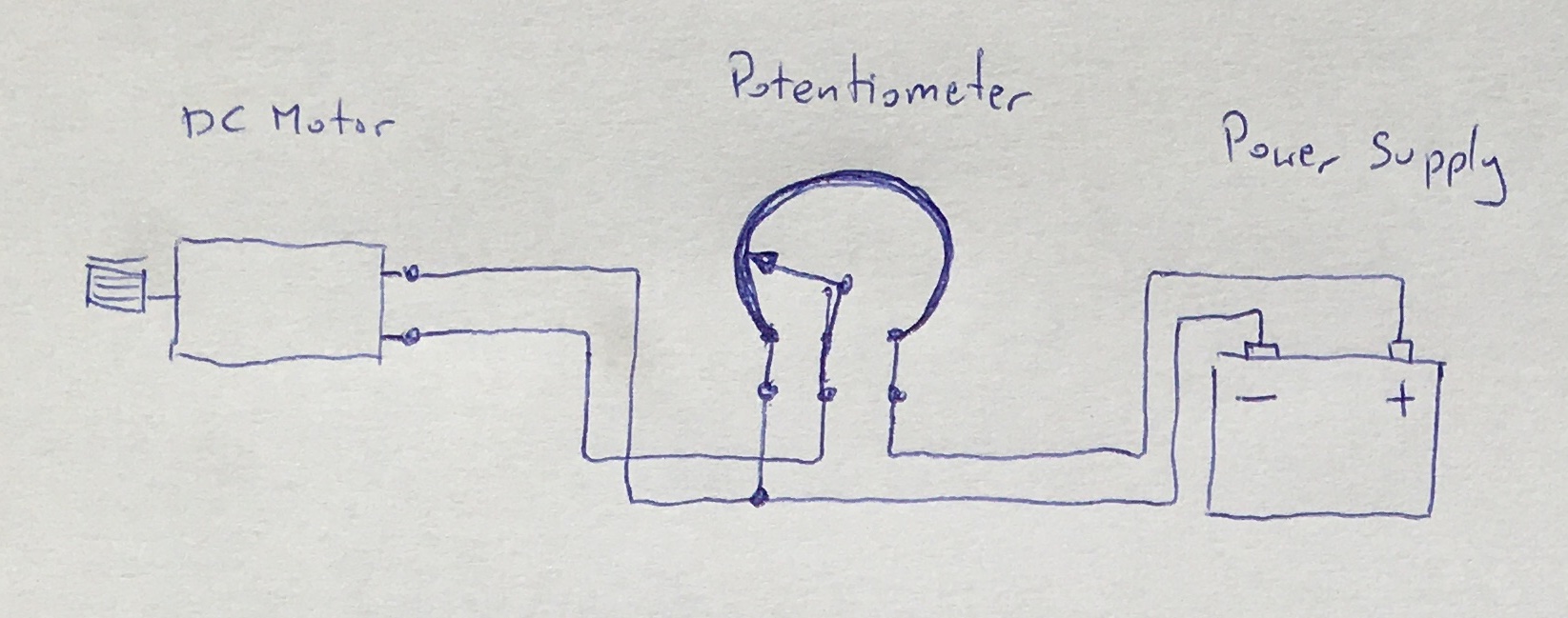
|
Using a voltage divider as a power source for almost anything is a very bad idea. A voltage divider is a very good way to get a lower voltage reference point but it cannot be used to deliver any power.
If you try to use it for this purpose it would be an extremely low efficient with low regulation performance vs. load changes. This is extremely well observed especially in case of application when the actual voltage supplied to the load vary with the load current... as this is in case of DC motors.
Remember: voltage divider is good only for low power constant load applications. And even if you see that someone use it, even with success, never do this. I've heard of people surviving a 10-story fall, but don't let that make me want to try it.
Explanation of why voltage divider doesn't work you will find in one of my next tutorials: see my Potentiometer tutorial.