
In this tutorial you will learn what a voltage divider is, how it works, when it can be use and when you should avoid it. You will work with potentiometer, which is a variable voltage divider, to find voltage ranges when microcontroller reads LOW and HIGH state on his digital input pins. The latter is very important in communication among different electronics components.
Table of contents
A voltage divider is one of the most fundamental circuits in electronics. It is a simple circuit which turns a large voltage into a smaller one. Using just two series resistors and an input voltage, you can create an output voltage that is a fraction of the input.
You may see it drawn a few different ways:

|
but they are always the same circuit. In this subsection you will denote the resistor closest to the input voltage $V_{in}$ as $R1$, and the resistor closest to ground as $R2$. The voltage drop across $R2$ is called $V_{out}$, and that is the divided voltage this circuit exists to make.
Formula used to calculate $V_{out}$ takes a form:
$$V_{out} = \frac{V_{in}R_{2}}{R_{1}+R_{2}}$$
For easier referrence I will call the point petween two resistors as divider point (point B in the picture below; it is called also as mid-terminal) and two other points as ground point (point C) and power point (point A):

|
Many sensors in the real world are simple resistive devices. A photocell is one of a such variable resistor, which produces a resistance proportional to the amount of light it senses: the more light we provide the lower resistance of photocell is.
It turns out voltage is really easy for microcontrollers (at least those with analog to digital converters, ADC’s) to measure. Things are not so simple with resistance. But, by adding another resistor to the resistive sensors, we can create a voltage divider. Thus instead of measure resistance, we can measure voltage.Once the output of the voltage divider is known, we can go back and calculate the resistance of the sensor.
Consider the following schema

|
where the symbol of resistor with two arrows pointing to it is a symbol of photoresistor. Taking the photoresistor with resistance between 0kO in the full light and about 10kΩ in the dark accompanied by 10kO resistor and powered by 5V power source, I got 0.0V when there was full light and 2.88V in the full dark. If accompanying resistor was 1kO, I got 0.62V when there was full light and 4.86V in the full dark.
| R1 | Voltage in full | |
| light | dark | |
| 10kO | 0.2 | 2.88 |
| 1kO | 0.62 | 4.86 |
These values are different from theoretical values obtained with voltage divider formula (maybe I made a mistake, maybe my measurement wasn't precise):
| R1 | Voltage in full | |
| light | dark | |
| 10kO | $V_{out} = \frac{V_{in}R_{2}}{R_{1}+R_{2}}=\frac{5V \cdot 0\Omega}{10k\Omega+0\Omega} = 0V$ | $V_{out} = \frac{V_{in}R_{2}}{R_{1}+R_{2}}=\frac{5V \cdot 10k\Omega}{10k\Omega+10k\Omega} = 2.5V$ |
| 1kO | $V_{out} = \frac{V_{in}R_{2}}{R_{1}+R_{2}}=\frac{5V \cdot 0\Omega}{1k\Omega+0\Omega} = 0V$ | $V_{out} = \frac{V_{in}R_{2}}{R_{1}+R_{2}}=\frac{5V \cdot 10k\Omega}{1k\Omega+10k\Omega} = 4.545V$ |
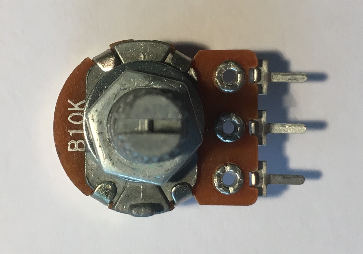
A potentiometer is a three-terminal resistor with a sliding or rotating contact (wiper):
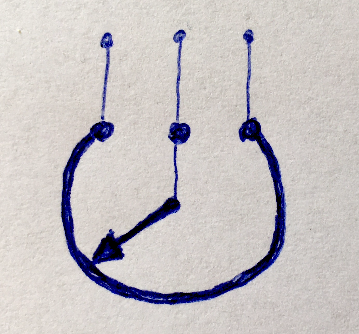
|
that forms an adjustable voltage divider. If only two terminals are used, one end and the wiper, it acts as a variable resistor.

|
|
We can think of a potentiometer as a variable voltage divider. Images below show all the possible states of a potentiometer and voltage dividers corresponding to them (notice that in this case voltage input and ground doesn't matter, so we skipped this element in the picture as well as we reverse order of resistors which again doesn't matter -- after all, it's just a matter of the agreement, which one we will call $R1$ and wich one $R2.)

|

|

|

|

|

|

|
Take the Arduino board and make the following test
- Turn potentiometer to one of its final position.
- Use middle potentiometer's pin output signal as input signal for digital and analog Arduino's pins
- In Arduino
- read digital pin value and print HIGH if this pin is in
HIGHstate and LOW if is inLOWstate - read analog pin value and print voltage
- read digital pin value and print HIGH if this pin is in
- Change, not to fast, potentiometer position to opposite final position. Doing this, read and print digital and analog values (see previous step). Note when digital state will switch to
HIGHwhen voltage is increased from 0V to 5V, and when digital state will switch toLOWwhen voltage is decreased from 5V to 0V.
Why you do this? Firstly, simply to observe how you can smoothly control voltage with potentiometer. Secondly, to find operational voltage ranges for microcontroller logic (in case of 5V logic). You will use this knowledge in one of my next tutorial (see my Different voltage level coexistence tutorial).

|

|
Below tere is a code we can use to make this test.
|
1 2 3 4 5 6 7 8 9 10 11 12 13 14 15 16 17 18 19 20 21 22 23 24 25 26 27 |
#define LED 13 #define SIGNAL 7 #define VOLTAGE A0 // the setup function runs once when you press reset or power the board void setup() { pinMode(SIGNAL, INPUT); pinMode(LED, OUTPUT); Serial.begin(9600); } // the loop function runs over and over again forever void loop() { byte value = digitalRead(SIGNAL); int sensorValue = analogRead(VOLTAGE); float voltage = sensorValue * (5.0 / 1023.0); Serial.println(voltage); if(value == HIGH) { digitalWrite(LED, HIGH); // turn the LED on (HIGH is the voltage level) } else { digitalWrite(LED, LOW); // turn the LED off by making the voltage LOW } } |
Read an appropriate documentation if you don't know how function we used are working
In my case
- when voltage is increased from 0V to 5V, digital state switches to
HIGHfor 2.7Vfilm.mov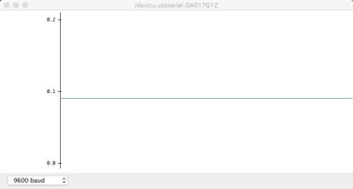

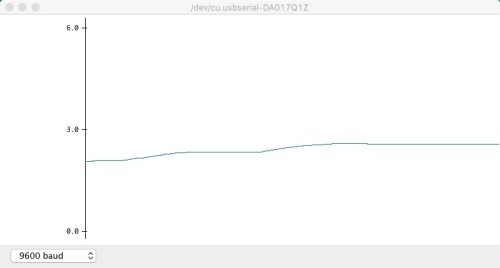
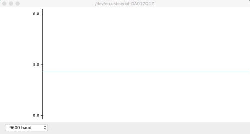
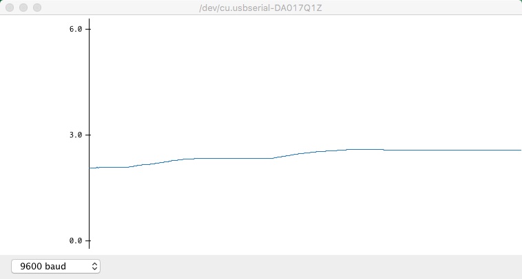
Top-left: Step 1, initial voltage about 0V, LOWstate; Top-right: Step 2; continue increasing voltage; Bottom-left: Step 3, still continue voltage increasing; Bottom-right: Step 4, state switches toHIGHstate, voltage about 2.7V
- when voltage is decreased from 5V to 0V, digital state switches to
LOWfor 2.16V.
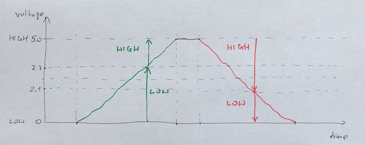


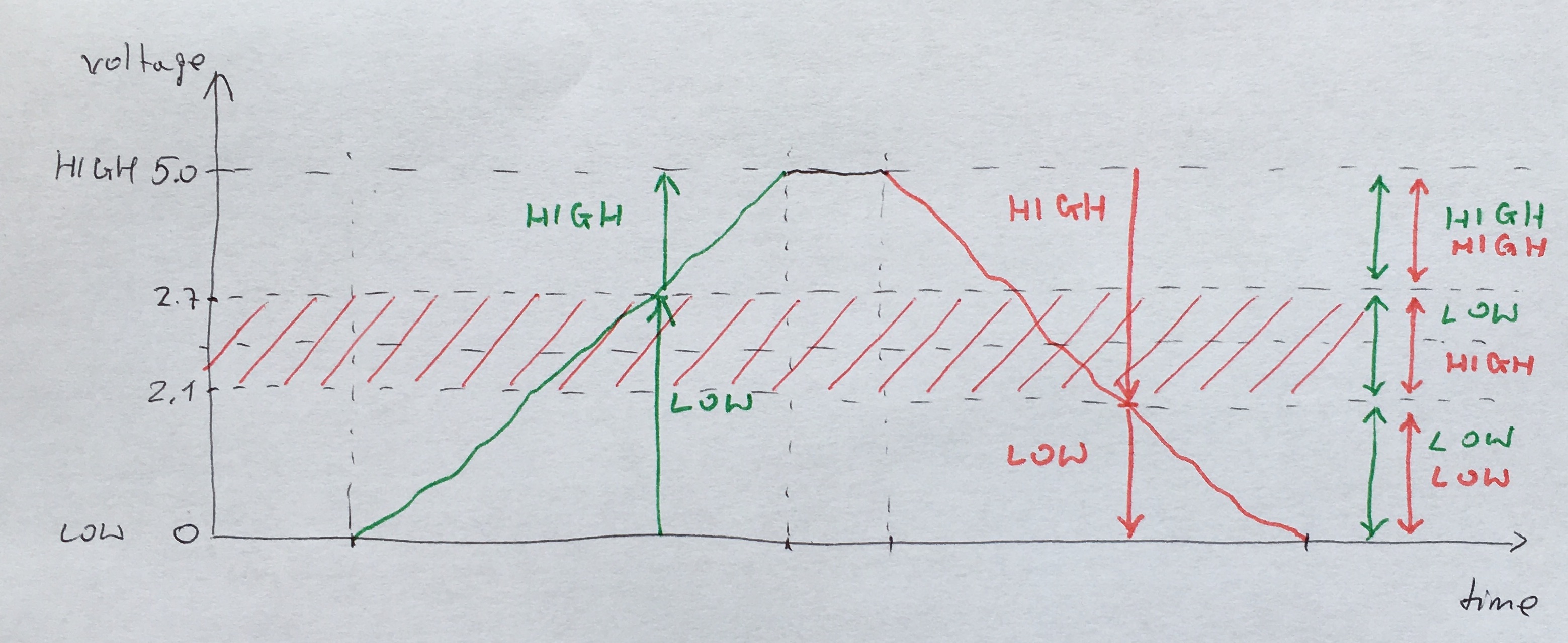
In result you will see three different ranges:

|
- Range in which, regardless whether the voltage was increased or decreased, digital state is always
LOW. - Range in which, regardless whether the voltage was increased or decreased, digital state is always
HIGH. - Range in which, sometimes digital state is
LOWbut other times it isHIGH.
In consequence, whenever voltage is in red range depicted below you cannot be sure about digital value microcontroller will read.
|
This behavior is correct and as expected -- see next section for more details.
This is a little bit off topic, but because you have just completed related test so I decided to continue this thread.
As you probably know, logic gate circuits are designed to input and output only two types of signals: HIGH corresponding to logic 1 or "true" and LOW corresponding to logic 0 or "false". Both are represented by a voltage: full power supply voltage for a HIGH state and zero voltage for a LOW state. However because of real world imperfection logic circuit signals rarely reach these extreme voltage limits -- they are close but almost never equal to them.
Knowing this, engineers proposed some acceptable ranges of values treated as a HIGH or LOW. These ranges depends on the technology used to produce gates: TTL or CMOS (I will not discuss here the differences between both technologies).
TTL gates operate on a nominal power supply voltage of 5 volts, +/- 0.25 volts. Ideally, a HIGH signal would be 5 volts exactly, and a LOW signal 0 volts exactly. In practice exact values may be difficult to obtain so gate circuits are designed to accept HIGH and LOW signals deviating substantially from these ideal values.
Acceptable input signal voltages range from 0 volts to 0.8 volts for a LOW logic state, and from 2 volts to 5 volts for a HIGH logic state.
Acceptable output signal voltages range from 0 volts to 0.5 volts for a LOW logic state, and from 2.7 volts to 5 volts for a HIGH logic state.
If a voltage signal ranging between 0.8 volts and 2 volts is sent into the input of a TTL gate, there would be no certain response from the gate. Such a signal is considered uncertain (undefined), and no logic gate manufacturer guarantee how their gate circuit interpret such a signal.
As you can see, the tolerable ranges for output signal levels are narrower than for input signal levels -- the difference between the tolerable output and input ranges is called the noise margin of the gate.
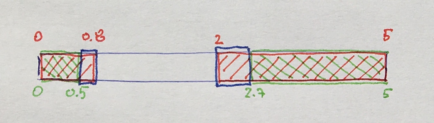
|
| Input range in RED, output range in GREEN and noise margin in BLUE |
CMOS gate circuits have input and output signal specifications that are quite different from TTL. First of all a CMOS gate can operate at a various power supply voltage $V_{DD}$. That is why acceptable input signal values for LOW and HIGH state are defined as percentage of $V_{DD}$:
- 0V to 30% of $V_{DD}$ for LOW,
- 70% $V_{DD}$ to $V_{DD}$ for HIGH.
Acceptable output signal voltages range from 0 volts to 0.05 volts for a LOW logic state, and $V_{DD}-0.05$ volts to $V_{DD}$ volts for a HIGH logic state.
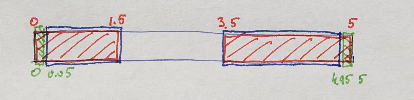
For a CMOS gate operating at a power supply voltage of 5 volts, the acceptable input signal voltages range from 0 volts to 1.5 volts for a LOW logic state, and 3.5 volts to 5 volts for a HIGH logic state.
Acceptable output signal voltages range from 0 volts to 0.05 volts for a LOW logic state, and 4.95 volts to 5 volts for a HIGH logic state.
From above you see that CMOS gate circuits have far greater noise margins than TTL. In case of 5 volts power suply you have 1.45 volts for CMOS low-level and high-level margins, versus a maximum of 0.7 volts for TTL. In other words, CMOS circuits can tolerate much more noisy signals on their inputs before interpretation errors will result.
|
| Input range in RED, output range in GREEN and noise margin in BLUE |
Going back to our test you see that Arduino is much more tolerant as it accepts all the signal in range from 0 to 2.1 volts as LOW state (instead of from 0 to 1.5 volts as it is defined in standard) and all the signal in range from 2.7 to 5 volts as HIGH state (instead of from 3.5 to 5 volts as it is defined in standard).
Now it's time to return to the issue that appeared in the previous tutorial Power: why voltage divider cannot be used to deliver voltage to devices requiring more than little power, like for example DC motors.
The reason is that, as you already know, the divider's output voltage is set by the ratio of the two resistors:

|
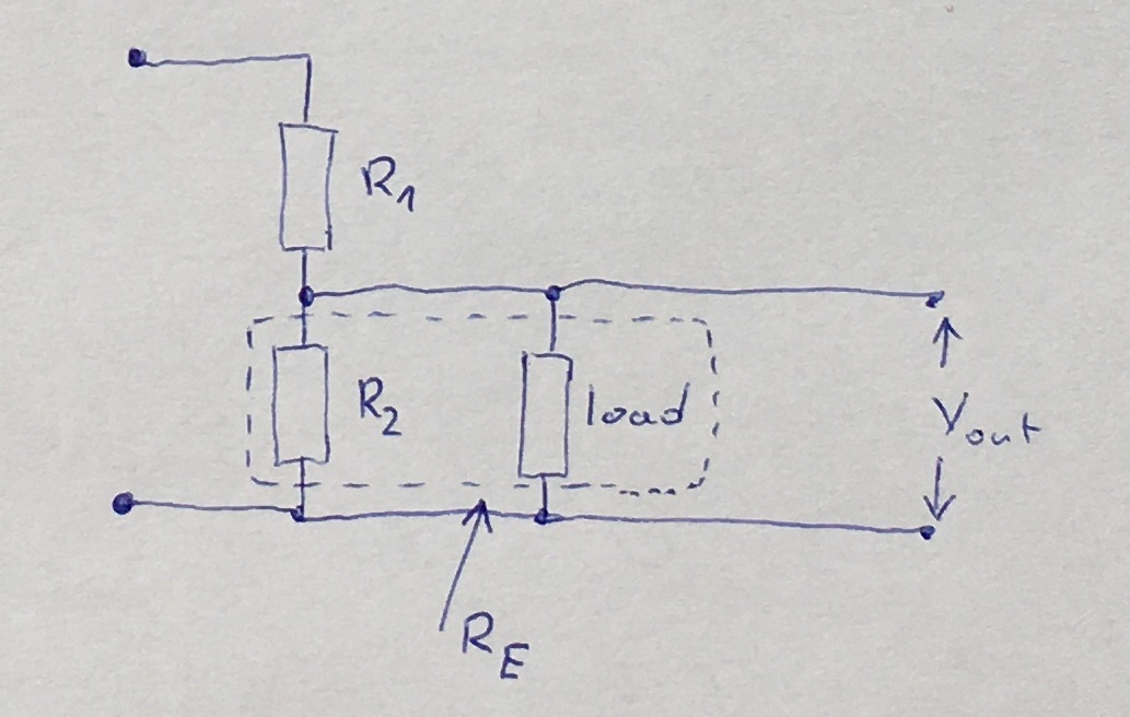
Any load you place across the divider will change the value of the resistor in the divider. When you connect a load its resistance becomes part of the resistor -- basically it is in parallel with one of the resistors. This changes the ratio and will make a dynamically changing divider voltage if the load changes dynamically, as it is in case of DC motors:
|
Suppose you have a 10V power source providing input voltage to your voltage divider and you use two 1kOhms resistors to get a 5V:
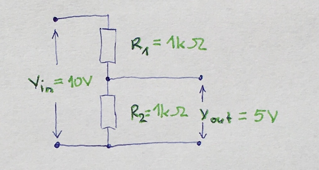
|
Then you have a load of 1Ohm that you want to power. If you connect the 1Ohm to the ground and the divider point it will be in parallel with the "lower" 1kOhms resistor:
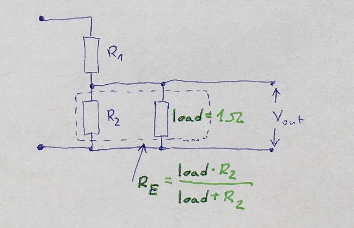
|
As you may remember from introductory part Basics the equivalent resistance of parallel resistors is always less than the smallest resistor and is calculated with the following formula (for $n$ resistors):
$$\frac{1}{R_{E}}=\frac{1}{R_{1}}+\dots+\frac{1}{R_{n}}$$
Thus it will be close to one ohm (0.999 actually) so you have a divider that has been changed its parameters from $R_1=1000 \Omega$ and $R_2=1000 \Omega$ to $R_1=1000 \Omega$ and $R_2=1 \Omega$ and now the output voltage from divider is equal to $(10 \cdot 1)/(1000 + 1) \approx 0.01$ volts instead of 5 volts.
By the way, you notice that connecting a resistor in series with load is very much the same as making a voltage divider circuit.
You can try and make both $R_1$ and $R_2$ smaller preserving their ratio so that the paralleled load has less effect on $R_2$. Suppose you change both to 10 Ohms or even 1 Ohm and keep 1 Ohm load. In such case you obtain:
|
1 2 3 4 5 6 7 8 9 |
R_1 = R_2 = 10 Ohms R_E = R_1/(R_1 + 1) = 10/11 = 0.9 V_out = (V_in * R_E)/(R_1 + R_E) = (10V * 0.9Ohms)/(10Ohms + 0.9Ohms) = 9VOhms/10.9Ohms = 0.826V R_1 = R_2 = 1 Ohm R_E = R_1/(R_1 + 1) = 1/2 = 0.5 V_out = (V_in * R_E)/(R_1 + R_E) = (10V * 0.5Ohms)/(1Ohms + 0.5Ohms) = 5VOhms/1.5Ohms = 3.33V |
As you can see, in each case applying load changes resulting output voltage from divider. In result, if your load has varying current requirements, your power supply voltage will fluctuate as a function of load current.
The line regulation of a voltage divider is very poor: if the input changes 100% so will the output. In consequence, the power supply output voltage will only be as stable as the input to the power supply.
Moreover the upper resistor $R_1$ limits the current to the rest of the your circuit.
Finally the power dissipation in the divider may be significant.